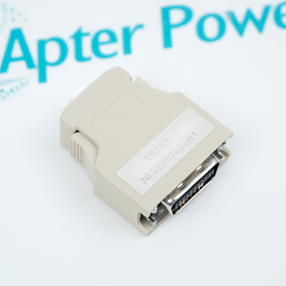
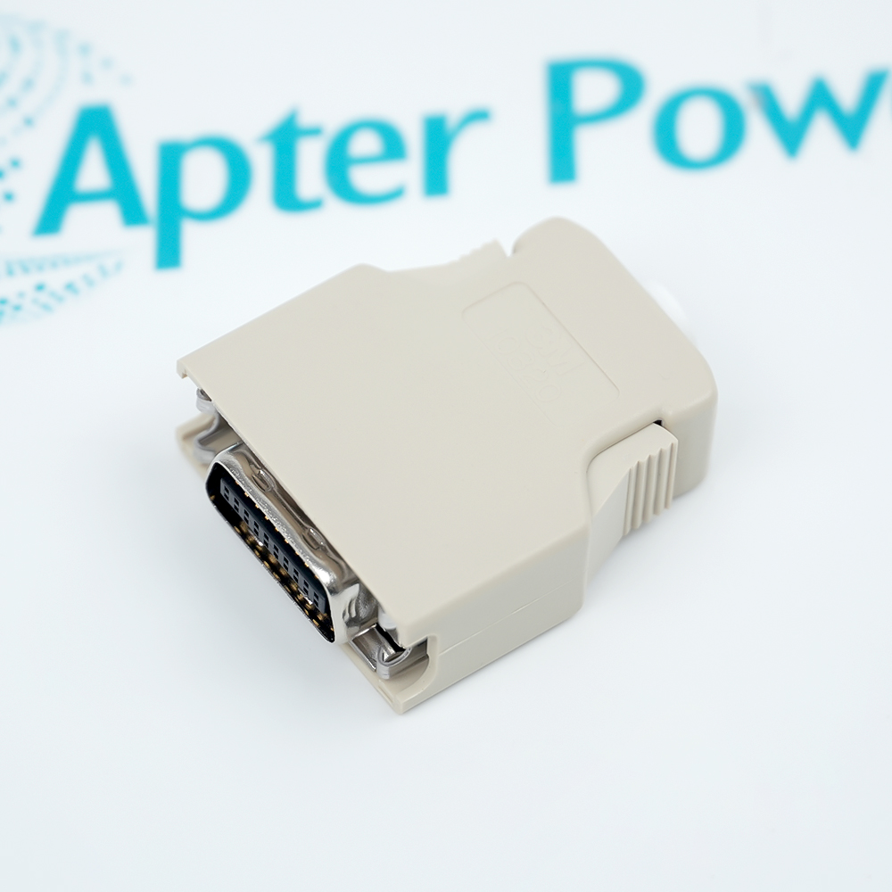
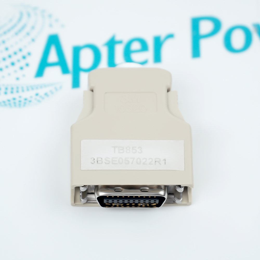
Completes the RCU Control Link at its designated endpoint so the controller communication line has the required termination.
- Signal or energy path: The unit is a passive communication accessory and does not convert, measure or generate a process signal.
- Companion components: Use it with the approved controller, RCU-link cable, redundancy arrangement and cabinet connection hardware for the installed system.
- Engineering check: Confirm endpoint location, cable continuity, connector engagement and the absence of an extra terminator before energizing the link.
- System boundary: The RCU link is terminated only at its documented endpoint; duplicate termination can prevent reliable communication.
AC 800M and System 800xA controller installations using an RCU communication link.
Important Notice: Verify the complete TB853 3BSE057022R1 nameplate, installed-system documentation, companion hardware and current ABB instructions before installation or replacement.
Apter Power TB853 3BSE057022R1 Manuals and Guides
Important Notice: The first link is the product-parameters PDF prepared only from the cited manufacturer information; the second link is the Apter Power product manual. Confirm the physical nameplate, current manufacturer documents, and host-system requirements before installation or replacement.
RCU Control Link termination
Terminates the RCU Control Link in the ABB AC 800M topology specified for the installed redundant controller configuration.
PM891 redundant control
Used in the RCU Control Link architecture associated with PM891; ABB lists TK856 as the PM891 RCU Control Link cable.
System 800xA controller cabinets
Applied as a communication-bus accessory where a System 800xA AC 800M controller design requires RCU Control Link termination.
Compact Product Suite cabinets
Applied in Compact Product Suite AC 800M redundant-controller layouts that use the RCU Control Link.
Read and follow the current ABB documentation and host-equipment instructions before work. Verify the complete physical nameplate and system configuration.
1
Verify both TB853 and article number 3BSE057022R1 on the physical label before installation.
2
Do not substitute TB852; ABB assigns TB852 to the RCU Link and TB853 to the RCU Control Link.
3
Verify the controller redundancy topology, PM891 hardware and the specified TK856 cable in the current ABB hardware documentation.
4
Isolate the controller system and follow ABB's qualified-personnel and hardware-handling procedures before connecting or removing the terminator.
5
Inspect and secure the connector, then validate redundant-controller diagnostics before returning the process system to service.