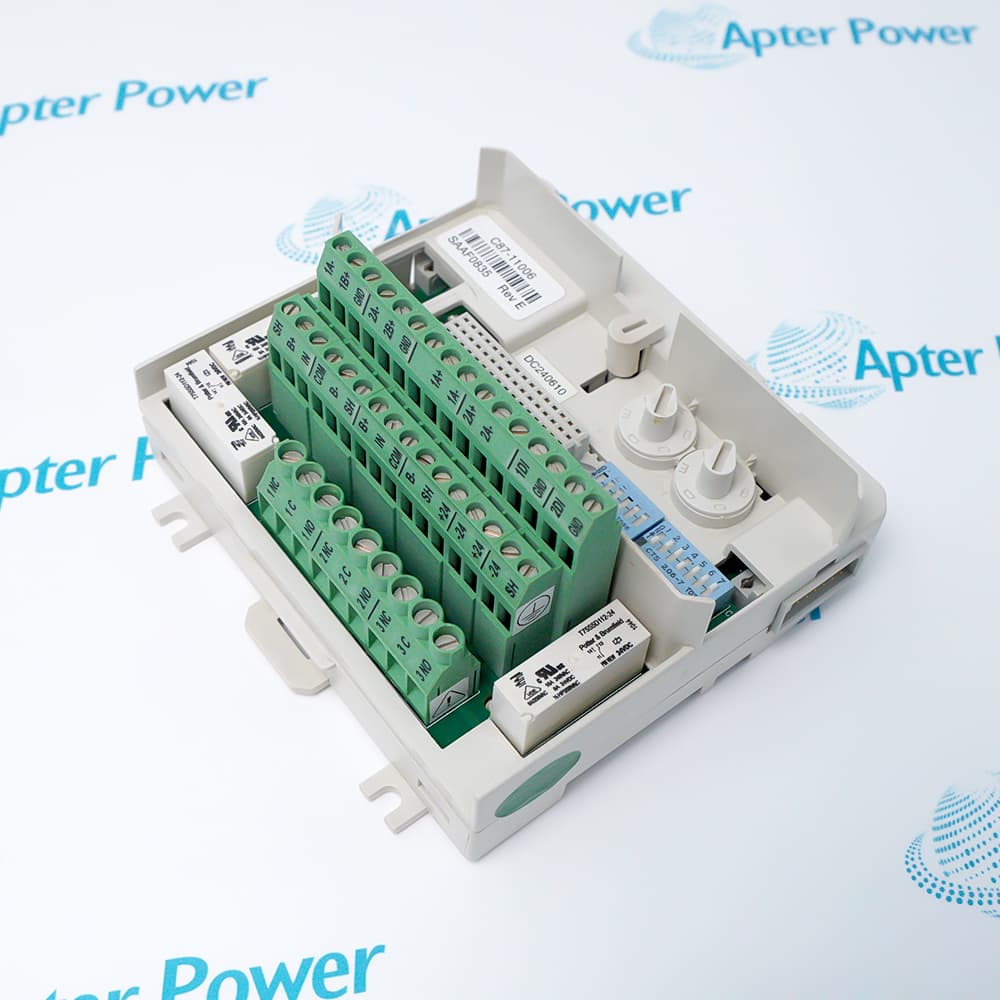
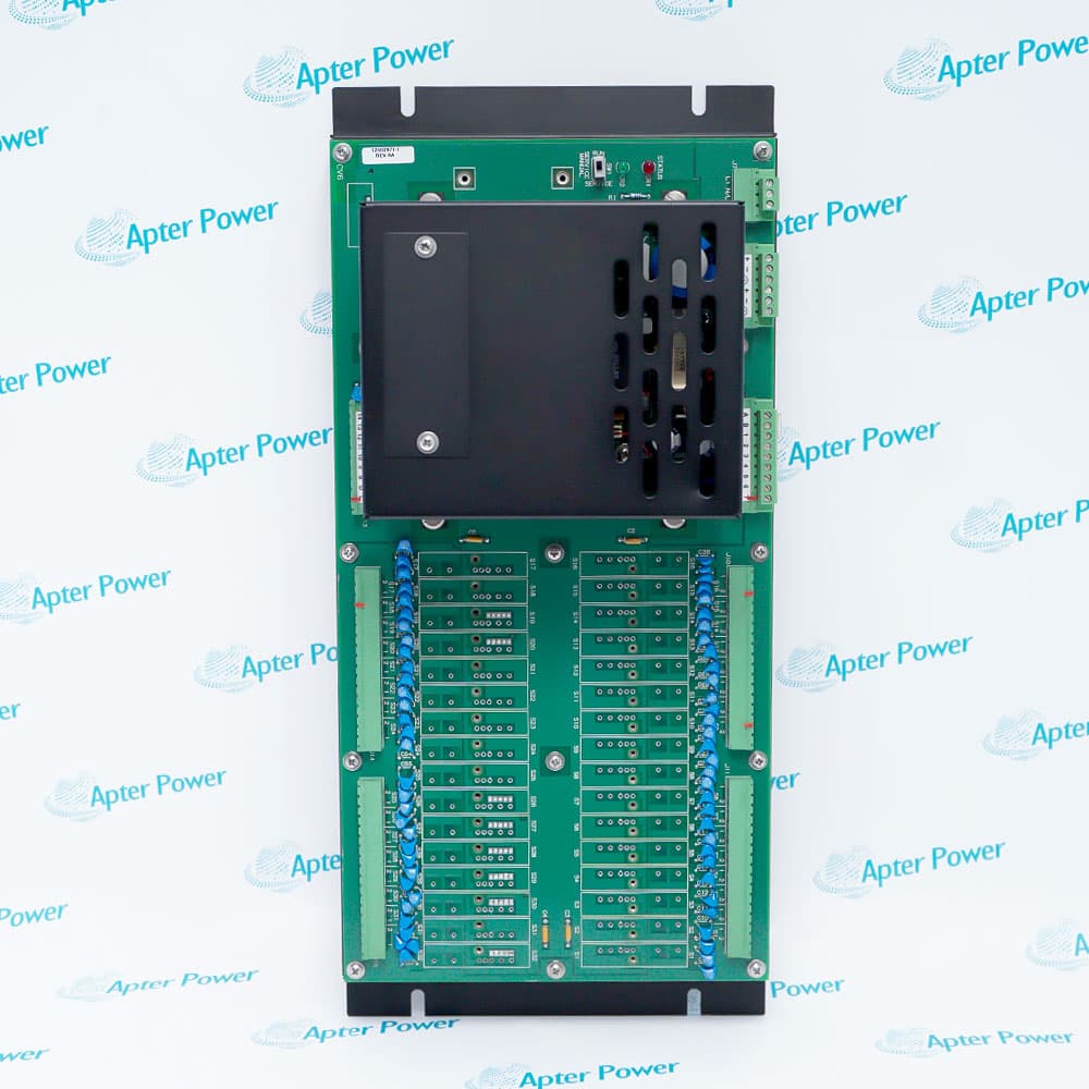
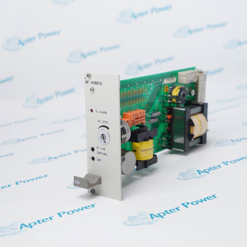
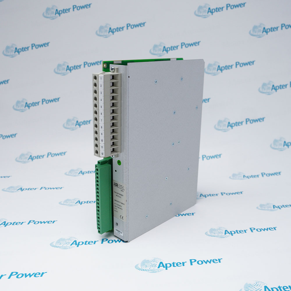
NTRL02B is the requested marking for a Bailey INFI 90 fiber-optic remote-link termination unit. Bailey instruction I-E96-429A documents the NTRL02 termination-unit function; the trailing B marking must be verified from the physical assembly because that suffix is not separately decoded in the cited instruction.
- NTRL02B
- NTRL02 / NTRL03 Termination Units, I-E96-429A
- Fiber-optic remote-link termination
- Attaches to an NFTP01 Field Termination Panel
The termination unit provides the cabinet interface between an IMRIO02 Remote I/O Slave Module and the remote-link/station-link wiring. Its TX and RX connections convert the remote-link path to fiber optics, while P1, P2 and P3 route module and station-link signals to the documented companion hardware.
Important Notice: Keep the complete NTRL02B marking unchanged and verify the physical nameplate, revision, companion hardware, and current manufacturer documentation before installation or replacement.
Apter Power NTRL02B Manuals and Guides
Important Notice: These are two separate Apter Power documents prepared from the manufacturer evidence named in each document. Confirm the physical nameplate, current manufacturer documentation, and applicable installation or system drawing before installation or replacement.
Control System Integration
INFI 90 distributed-control cabinets that require electrically isolated remote I/O or station-link communications between local and remote locations.
Signal and Data Handling
Fiber-optic remote-link communications and station-link signals. It does not independently measure analog, discrete, thermocouple or RTD field inputs.
Companion Hardware
IMRIO02 Remote I/O Slave Module, NFTP01 Field Termination Panel, NTCS04 termination unit where analog-bypass station-link service is required, approved fiber-optic cable and documented station/indicator connections.
Commissioning and Verification
Use NTRL02B only after confirming its complete nameplate, revision, configuration, connections, and every affected system function.
Read and follow the named manufacturer source and applicable installation instructions before use. Verify the exact complete ordering code from the physical nameplate.
1
Verify that the physical unit is marked NTRL02B and record its complete assembly and revision identifiers.
2
Calculate the optical power budget and use Bailey-recommended fiber and connectors for the installed route.
3
Confirm P1, P2, P3, TB1, fuse and jumper arrangements against the applicable system drawing before energization.
4
Observe the applicable wiring, grounding, approval, environmental and enclosure requirements.
5
Record the complete model, revision, configuration and commissioning results before returning the system to service.


 Videos
 News
News Applications