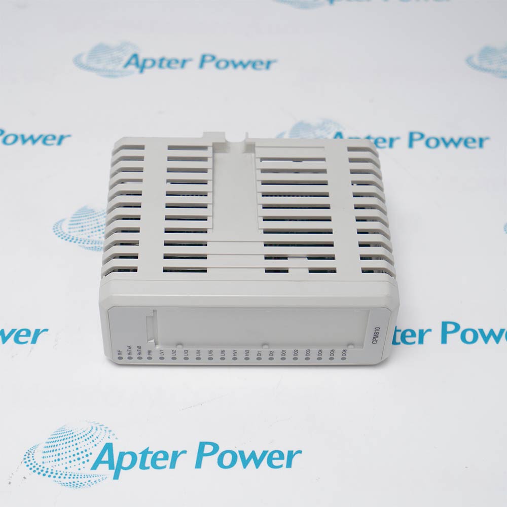
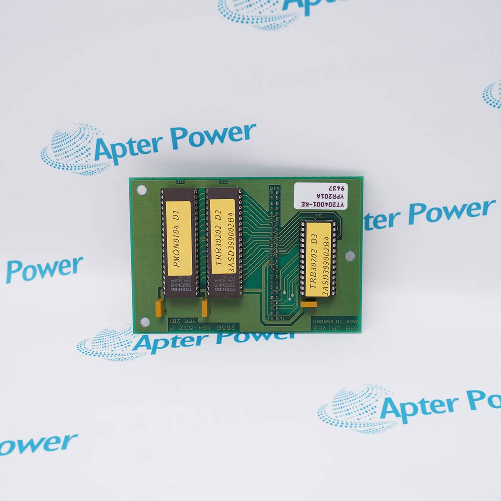
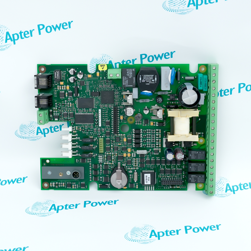
ABB IMSED01 is a Harmony Sequence of Events Digital Input module. ABB identifies it as a rack I/O module that processes as many as 16 digital field inputs for a Harmony controller and makes those channels available through the controller's sequence-of-events interface.
- Digital field inputs: Up to 16
- Input channel isolation: Each channel optically isolated
- Individually programmable input selections: 24 VDC ±10%; 48 VDC ±10%; 125 VDC ±10%; 120 VAC ±10%
- Controller interface function code: Function code 242, SOE digital event interface
The module communicates with its Harmony controller over the I/O expander bus. ABB permits up to 63 IMSED01 modules on one I/O expander bus segment together with one IMSET01 timing module, which establishes that the two products are complementary modules rather than aliases or merge candidates. Each input channel is optically isolated and individually programmable for 24 VDC, 48 VDC, 125 VDC, or 120 VAC input. ABB specifies that the 120 VAC selection is only for system control logic, and identifies NTDI01 as the field-wiring termination; a separate ABB rack-termination table also associates NTBMN2 with IMSED01. ABB's dated 2012 lifecycle presentation placed IMSED01 in the Active Harmony Rack I/O family, but this research did not locate a current exact-model lifecycle announcement. Any product page must therefore present the verified identity and historical evidence without claiming a current lifecycle phase, origin, tariff code, weight, or replacement that ABB has not explicitly documented.
Important Notice: Verify the complete ABB IMSED01 nameplate and current project documentation before use.
Apter Power IMSED01 Manuals and Guides
Important Notice: The first link is the model-specific product-parameters PDF prepared only from the cited ABB official evidence; the second link is the Apter Power product information manual. Confirm the physical nameplate, current ABB documents, and host-system requirements before installation or replacement.
Digital event acquisition in Harmony rack I/OCollect up to 16 supported digital field states for controller-based sequence-of-events processing where the installed voltage class and termination are verified against the ABB design.
Distributed SOE channel expansionAdd event-input capacity on an I/O expander bus segment under ABB's stated limit of up to 63 IMSED01 modules with one IMSET01 timing module.
Trip and interlock chronology inputsAcquire optically isolated digital indications used in a site's event chronology, provided system engineering confirms the required timestamping architecture and field voltage selection.
Maintenance of installed Symphony Harmony systemsIdentify and replace an exact IMSED01 position only after revision, termination, channel configuration, bus address, and lifecycle/service availability are checked.
Read and follow the exact ABB documentation and host-equipment instructions before work. Verify the complete physical nameplate and system configuration.
1Do not substitute IMSET01 for IMSED01 or merge their records; IMSED01 does not process the time-synchronization link.
2Keep the segment population within ABB's limit of up to 63 IMSED01 modules with one IMSET01 timing module.
3Verify every channel's configured voltage class before energizing field wiring; 24 VDC, 48 VDC, 125 VDC, and 120 VAC are distinct selections.
4Use 120 VAC inputs only for system control logic, as expressly qualified by the ABB data sheet.
5Confirm the installed termination topology. NTDI01 is the field-wiring termination named in the SOE data sheet, while NTBMN2 is an additional model association in the separate rack-termination table; do not assume unrestricted interchangeability.
6Observe the published noncondensing humidity, temperature, pollution-degree, altitude, and noncorrosive-atmosphere limits.
7Confirm the +5 VDC supply tolerance and cabinet power budget before installation.
8Treat the document-era CE and approval statements only in their stated installation context and verify current project certifications separately.
9Do not publish or use reseller-derived weight, dimensions, origin, HS code, channel current, or response-time values.
10Use qualified control-system personnel and preserve the original bus address, function-code configuration, termination, and wiring records during maintenance.


 Videos
 News
News Applications