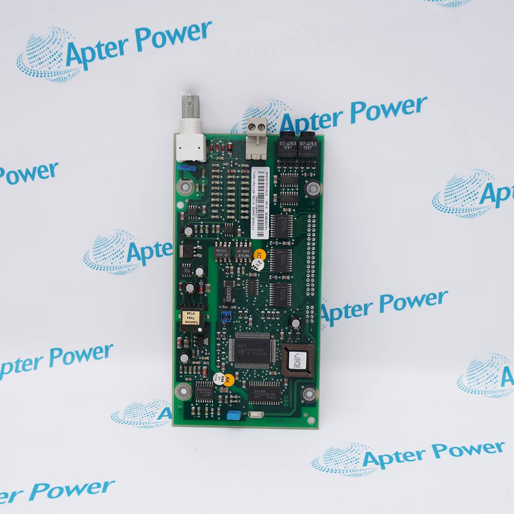
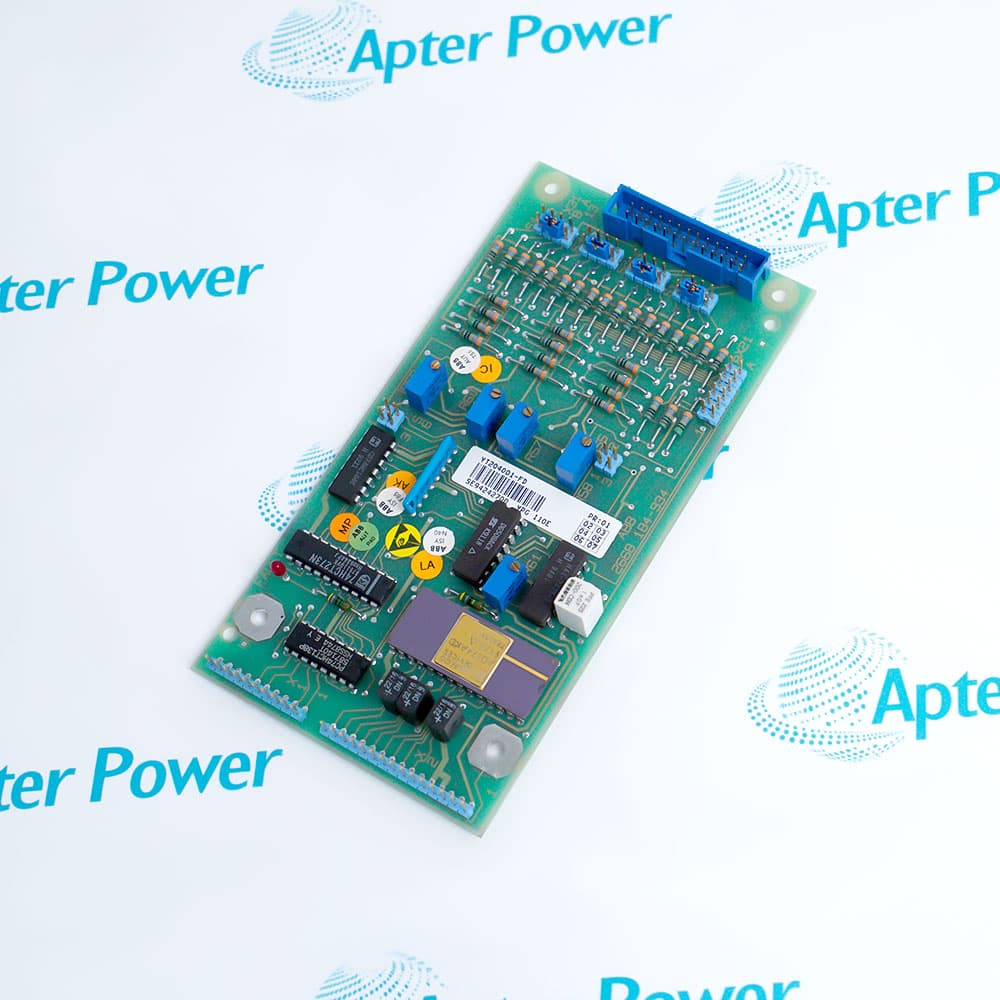
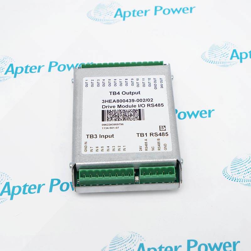
The ABB/Bailey IMRIO02 is a remote I/O communications module used with a Multi-Function Processor to communicate with remotely located slave modules in an INFI 90 control system.
- Remote I/O communications module
- INFI 90 / Symphony Harmony installed base
- IMMFP01, IMMFP02 or IMMFP03
- One module mounting unit slot
It carries remote I/O communications between the controlling MFP and remote slave-module locations. The module occupies one module-mounting-unit slot and works with the applicable remote-link termination hardware. Actual discrete or analog field signals are processed by the remote slave I/O modules, not by the IMRIO02 itself.
Important Notice: Keep the complete IMRIO02 marking unchanged and verify the physical nameplate, revision, companion hardware, and current ABB/Elsag Bailey documentation before installation or replacement.
Apter Power IMRIO02 Manuals and Guides
Important Notice: These are two separate Apter Power documents prepared from the official ABB/Elsag Bailey source named in each document. Confirm the physical nameplate, current manufacturer documentation, and applicable installation or system drawing before installation or replacement.
Control System Integration
Distributed process I/O where field modules are located remotely from the main INFI 90 Process Control Unit.
Signal and Data Handling
Remote I/O communications link data; field signal types are determined by the connected slave modules.
Companion Hardware
IMMFP01, IMMFP02 or IMMFP03 Multi-Function Processor; remote slave I/O modules; matching termination and cabling hardware.
Commissioning and Verification
Use IMRIO02 only after confirming its complete nameplate, revision, configuration, connections, and affected system functions.
Read and follow the official manufacturer source and applicable installation instructions before use. Verify the exact complete ordering code from the physical nameplate.
1
An IMRIO22/H-Net modernization is a system change; follow the ABB kit prerequisites and engineering procedure rather than treating it as an undocumented drop-in swap.
2
Record the complete remote-link topology, termination hardware and MFP configuration before replacement.
3
Verify communications and every affected remote I/O point before returning the system to service.
4
Observe the applicable wiring, grounding, approval, environmental, and enclosure requirements.
5
Record the complete model, revision, configuration, and commissioning results before returning the system to service.


 Videos
 News
News Applications