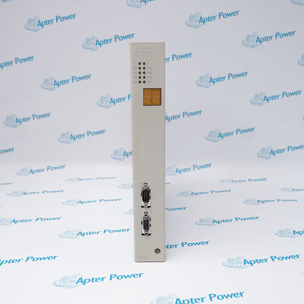
ABB IMHSS03 is an intelligent Harmony Rack hydraulic servo module for valve-position control. A Harmony controller uses function code 55 or 150 to configure and access its input and output channels.
- Function: Hydraulic servo valve-position control
- Controller functions: Function code 55 or 150
- Power: +5 VDC at 576 mA; +15 VDC at 15 mA; -15 VDC at 12 mA; +24 VDC at 335 mA from termination unit, all typical with ABB tolerances
- LVDT secondary inputs: 4 analog inputs total; 2 LVDT secondary inputs, each with 2 secondaries; 24 Vpp +/-7 VDC common mode; 10 kohm differential input impedance
The module drives a servo valve or I/H converter to move a hydraulic actuator and uses LVDT feedback to measure actuator position. ABB lists steam-turbine throttle and control valves, gas-turbine fuel valves, inlet guide vanes, and nozzle angle among its typical uses. IMHSS03 provides two LVDT primary excitation outputs, four LVDT secondary analog inputs, protected redundant servo-coil outputs, I/H converter capability, scaled and unscaled feedback/test outputs, three isolated contact inputs, and one isolated open-collector hard-manual output. The module occupies one MMU slot and works with IMFCS01 in most turbine-control applications. ABB later introduced SPHSS13 as a direct replacement platform for IMHSS03 and documented continued use of NTHS03 and NKHS03 in that evolution path.
Important Notice: Confirm the full IMHSS03 nameplate and revision, installed function code, LVDT type, servo/IH mode, and field wiring.
Apter Power IMHSS03 Manuals and Guides
Important Notice: The first link is the product-parameters PDF prepared only from the cited manufacturer information; the second link is the Apter Power product manual. Confirm the physical nameplate, current manufacturer documents, and host-system requirements before installation or replacement.
Steam-turbine valve positioning
Controls throttle, governor, and control-valve actuator position using LVDT feedback.
Gas-turbine fuel-valve control
Regulates servo current to position fuel valves and influence turbine speed.
Inlet guide vane positioning
Provides closed-loop hydraulic actuator control for guide-vane position.
Nozzle-angle control
Controls hydraulic nozzle-position mechanisms with redundant feedback/output arrangements.
Read and follow the current ABB documentation and host-equipment instructions before work. Verify the complete physical nameplate and system configuration.
1
Treat turbine hydraulic control as critical equipment and use an approved outage, bypass, and rollback plan.
2
Back up function-code configuration, calibration, gains, limits, polarity, servo mode, and alarms before service.
3
Verify the exact LVDT type, excitation frequency, wiring, common mode, impedance, and mechanical calibration.
4
Confirm servo-coil or I/H converter current range and load impedance before energizing outputs.
5
Verify NTHS03/NKHS03, jumpers, dipshunts, shields, field power, and hard-manual wiring against approved drawings.


 Videos
 News
News Applications