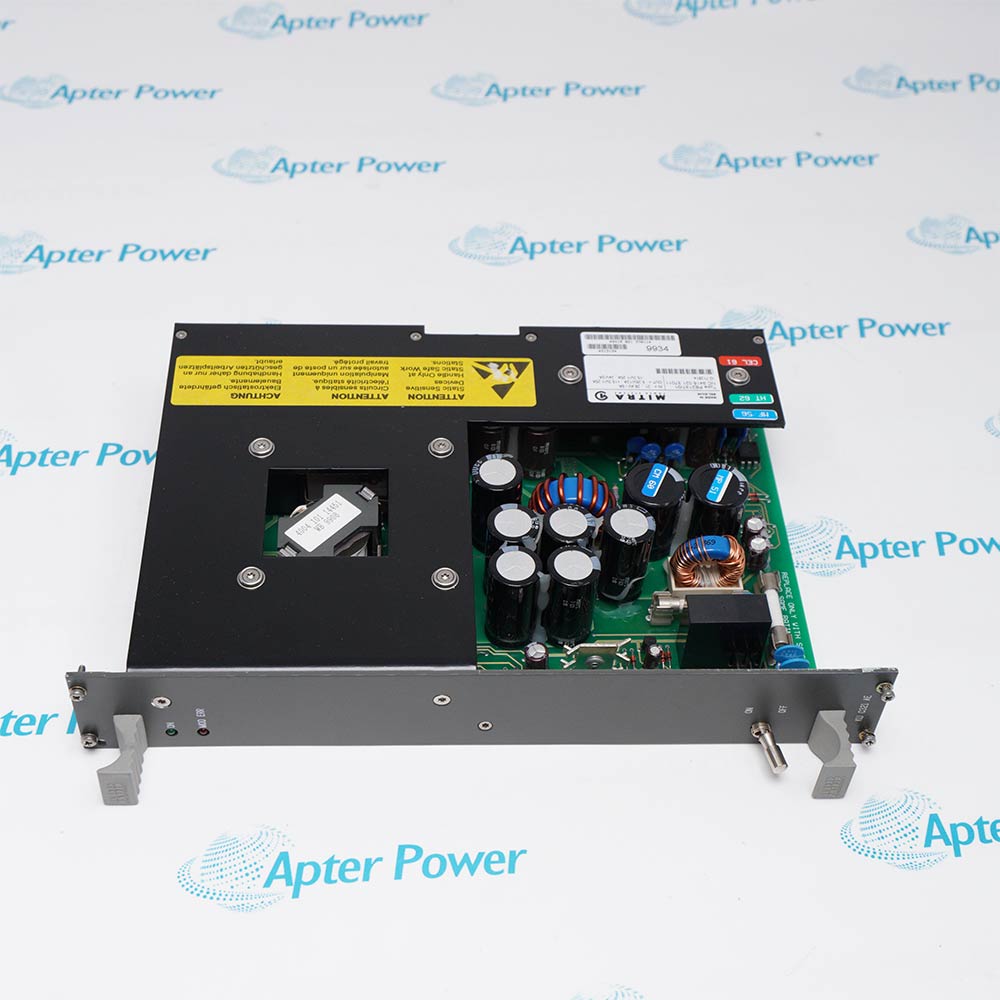
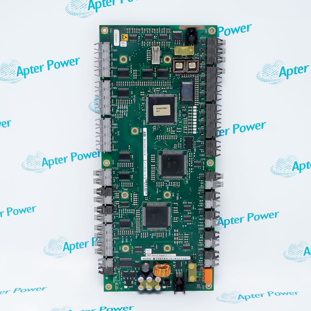
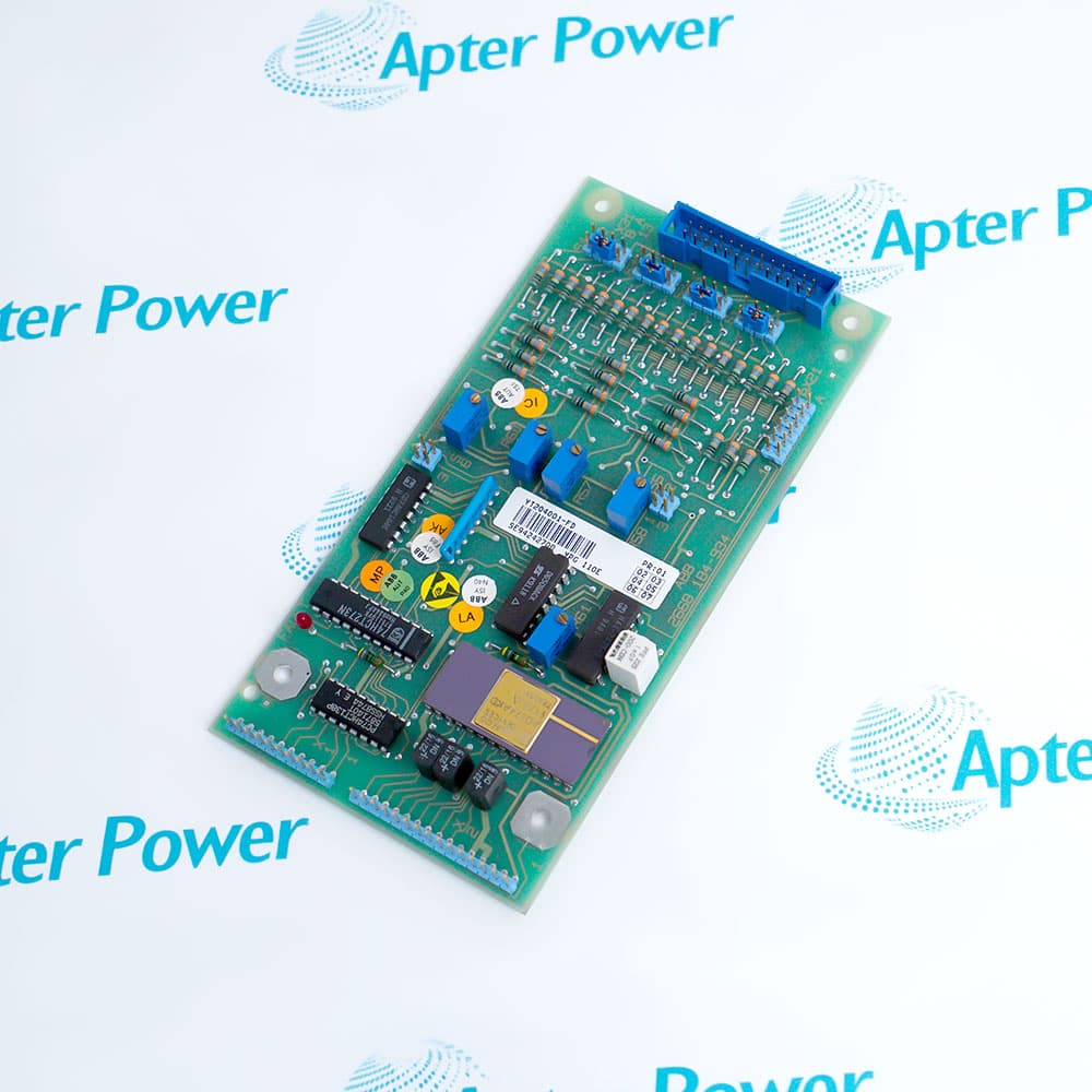
ABB IMDSI02 is a legacy sixteen-channel digital input module used in the INFI 90 and Harmony Rack installed-base evolution path. ABB's official mapping identifies the exact model and its supported 24 VDC, 125 VDC, and 120 VAC input classes.
- Product type: Legacy digital input module
- Channels: 16 digital inputs
- Documented input classes: 24 VDC, 125 VDC, and 120 VAC
- Isolation: Inputs optically isolated; ABB documents shared commons for pairs 7/8 and 15/16
The module receives discrete field states and presents them to the control system for status monitoring, permissives, alarms, and interlock logic. ABB documents optical isolation, with a specific termination boundary: channels 7 and 8 share one common, channels 15 and 16 share another, and the two channels in each pair must use the same voltage source. In the Harmony Rack architecture, field wiring is routed through a model-appropriate termination unit and cable and I/O data is exchanged with the controller over the I/O Expander Bus. ABB maps IMDSI02 to SPDSI22 as an engineered replacement path; SPDSI22 is not an alias, and its detailed ratings must not be copied to IMDSI02. Typical system duties include reading contact states, equipment-running feedback, protective trips, and process permissives in legacy industrial control panels. Before continued service or migration, engineers must verify the nameplate, input voltage class, shared-common grouping, termination, cable, addressing, controller configuration, and field-source segregation against the installed drawings and current ABB instructions.
Important Notice: Do not merge IMDSI02 with IMDSI22; the latter is a distinct model and a known Apter record ID 855791.
Apter Power IMDSI02 Manuals and Guides
Important Notice: The first link is the model-specific product-parameters PDF prepared only from the cited ABB official evidence; the second link is the Apter Power product information manual. Confirm the physical nameplate, current ABB documents, and host-system requirements before installation or replacement.
Equipment status monitoringReads verified discrete running, stopped, ready, and fault states.
Alarm and trip acquisitionBrings isolated field alarm or protective-trip states into legacy control logic.
Permissive and interlock inputsSupplies on/off conditions used by controller sequencing after voltage and common checks.
Engineered Harmony migrationSupports controlled assessment toward SPDSI22 while preserving field-source and termination constraints.
Read and follow the exact ABB documentation and host-equipment instructions before work. Verify the complete physical nameplate and system configuration.
1Verify the full IMDSI02 nameplate and revision; do not substitute IMDSI22 or SPDSI22 data.
2Confirm every channel's field voltage is one of the exact classes documented for IMDSI02.
3Keep channels 7/8 on the same voltage source and channels 15/16 on the same voltage source because each pair shares a termination-unit common.
4Confirm the exact termination unit, cable, commons, polarity, shielding, and field-source segregation from approved drawings.
5De-energize and apply the site electrical-safety procedure before disturbing field wiring; do not assume hot removal is safe.
6Back up I/O addressing, controller configuration, alarm logic, and interlock mapping before replacement or migration.
7Loop-check all sixteen channels and validate normal, alarm, open-circuit, and fail-state behavior after work.
8Keep function code, SOE capability, thresholds, response time, power, temperature, dimensions, weight, origin, HS code, and formal lifecycle phase HOLD until exact ABB evidence is obtained.


 Videos
 News
News Applications