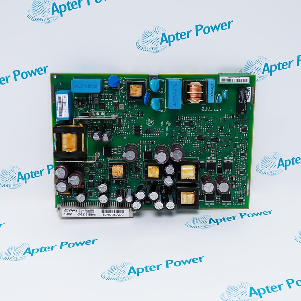
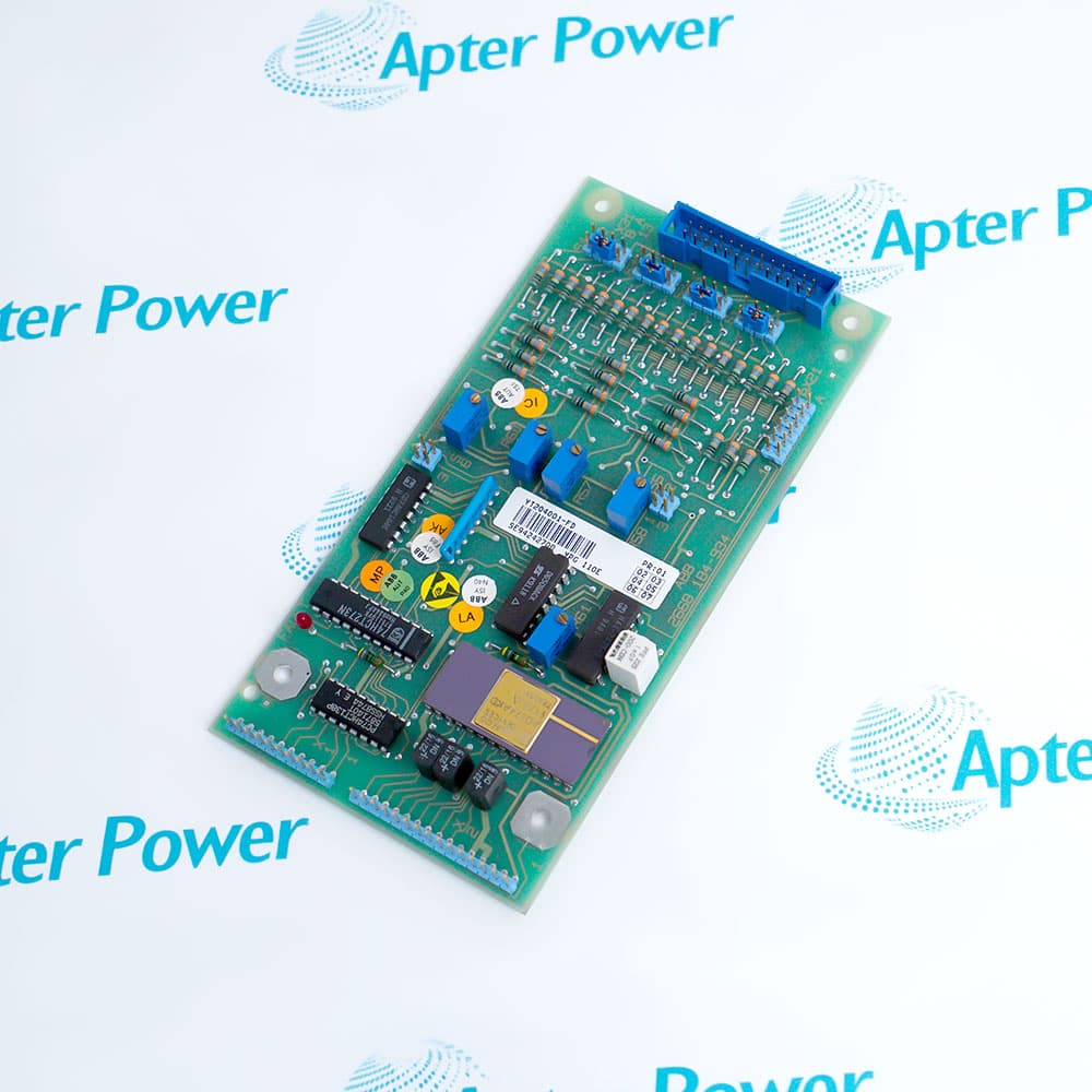
ABB IMASI13 is a 16-channel analog input module for the INFI 90/Harmony rack I/O architecture. Its official instruction identifies independently selectable analog input functions, allowing one module to acquire supported current, high-level voltage, millivolt, thermocouple, and RTD signals under controller configuration.
- Input channels: 16
- A/D resolution: 24-bit architecture
- Input classes: Current, high-level voltage, millivolt, thermocouple, and RTD
- Channel configuration: Input type and resolution independently selectable by channel
ABB documents 24-bit analog-to-digital conversion, channel isolation, open-input detection, automatic factory calibration and recalibration, engineering-unit conversion, and temperature-measurement compensation functions. These capabilities depend on correct channel type, range, wiring, function-code values, and controller configuration rather than automatic recognition of any connected signal. The IMASI13 instruction associates the module with the NTAI06 termination unit through NKAS01 or NKAS11 cable arrangements. ABB termination documentation also identifies NTBMJ2 for 16 system-powered two-wire 4-20 mA inputs with IMASI13; these are configuration-specific termination choices and must not be treated as interchangeable without the exact rack and wiring design. ABB includes a procedure for replacing IMASI03 with IMASI13 and notes required modifications. Separate ABB repair material says YIMASI13 is replaced with YIMASI23. These are migration or service relationships, not proof that IMASI03, IMASI13, and IMASI23 are the same hardware, so each model retains a distinct identity and its unsupported lifecycle and trade fields remain on HOLD.
Important Notice: Verify the complete ABB IMASI13 nameplate and current project documentation before use.
Apter Power IMASI13 Manuals and Guides
Important Notice: The first link is the model-specific product-parameters PDF prepared only from the cited ABB official evidence; the second link is the Apter Power product information manual. Confirm the physical nameplate, current ABB documents, and host-system requirements before installation or replacement.
Two-wire process transmittersAcquire engineered 4-20 mA loops, including the NTBMJ2 system-powered arrangement when that exact ABB topology is specified.
Thermocouple and RTD measurementProcess supported temperature sensors with the correct sensor curve, wiring, cold-junction, and lead-resistance configuration.
Voltage and millivolt acquisitionDigitize supported high-level and low-level voltage signals in Harmony rack applications after grounding and isolation review.
IMASI03 migrationReplace an IMASI03 only through ABB's documented IMASI13 procedure and the project's management-of-change controls.
Read and follow the exact ABB documentation and host-equipment instructions before work. Verify the complete physical nameplate and system configuration.
1Confirm the exact IMASI13 model, assembly revision, and rack location before any work.
2Back up all function codes, channel types, ranges, scaling, calibration, alarm, and controller configuration data.
3Do not replace IMASI03 with IMASI13 without applying the modifications in the ABB instruction and validating power and configuration.
4Verify whether the installation uses NTAI06 with NKAS cabling or the configuration-specific NTBMJ2 current-input topology; never interchange termination arrangements by assumption.
5Check sensor type, loop polarity, grounding, shielding, isolation, and transmitter power before energization.
6Apply ABB electrostatic-discharge controls and approved powered-rack service procedures while maintaining process safeguards.
7Perform a complete loop check, open-input diagnostic check, and engineering-unit comparison after installation or replacement.
8Treat YIMASI13 as a repair-service material and IMASI23 as a distinct successor relationship, not as aliases for canonical publication.
9Do not publish lifecycle phase, origin, HS code, weight, or dimensions without exact ABB model-level evidence.


 Videos
 News
News Applications