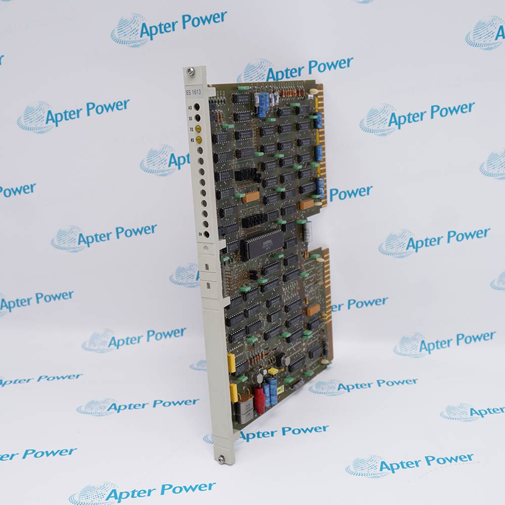
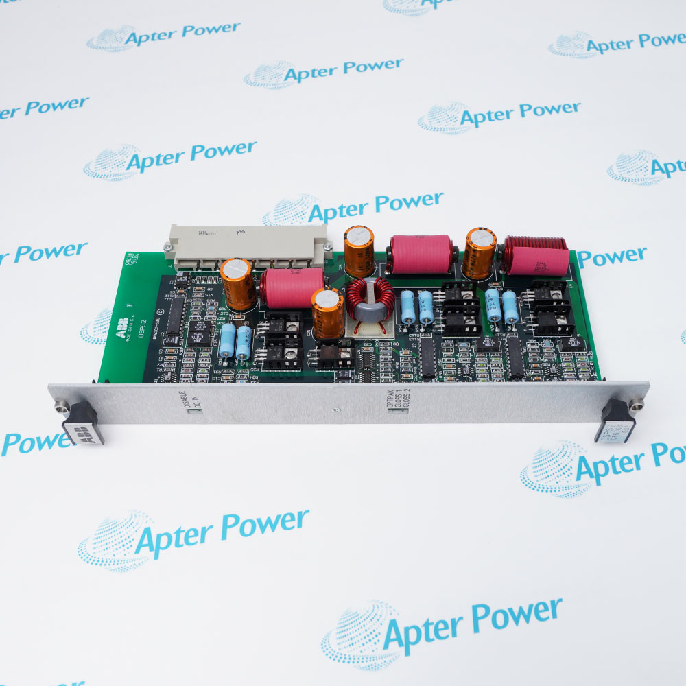
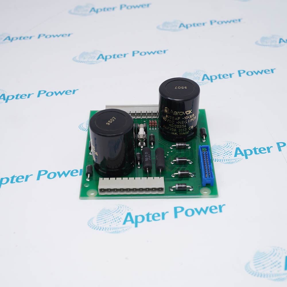
ABB FEN-31 is an HTL encoder interface installed between a compatible ABB drive control board and an HTL encoder.
- A, B and Z HTL encoder inputs, up to 300 kHz
- Encoder supply: +15 V DC or +24 V DC, plus or minus 20%, 200 mA
- Isolated A, B and Z encoder-emulation output over RS-422/485, up to 500 kHz
- Two short-circuit-proof 24 V digital latch inputs
It receives speed, direction, position and reference-mark pulses, supplies this feedback to the drive, and can reproduce isolated encoder signals for compatible downstream equipment in closed-loop drive-controlled machinery.
Important Notice: ABB directly verifies current loose-item code 68978955; requested code 68978840 must be confirmed from the physical ABB nameplate or a direct ABB spare-parts record before it is treated as an exact legacy code.
Apter Power FEN-31 68978840 Manuals and Guides
Important Notice: The first link is the product-parameters PDF prepared only from the cited manufacturer information; the second link is the Apter Power product manual. Confirm the physical nameplate, current manufacturer documents, and host-system requirements before installation or replacement.
Closed-loop speed feedback
Supplies A and B pulse feedback to a compatible ABB drive for closed-loop speed control.
Position and reference feedback
Uses A, B and Z channels for position, direction and reference-mark information.
Encoder-based process control
Supports drive-controlled machinery whose configured control functions depend on HTL encoder feedback.
Isolated signal replication
Provides an isolated A, B and Z TTL encoder-emulation output to compatible downstream equipment.
Follow the applicable ABB drive and FEN-31 instructions, and confirm host-drive compatibility before installation or commissioning.
1
Installation and maintenance are for qualified electricians only.
2
Isolate every power source, prevent reconnection, wait five minutes and verify that the drive is discharged before work.
3
Earth the drive and module correctly because the grounding screw is important for EMC performance.
4
Use shielded instrumentation cable, preferably twisted pairs, and separate encoder wiring from motor and power cables.
5
Connect a supported motor-temperature sensor only when it has double or reinforced insulation from live motor parts.


 Videos
 News
News Applications