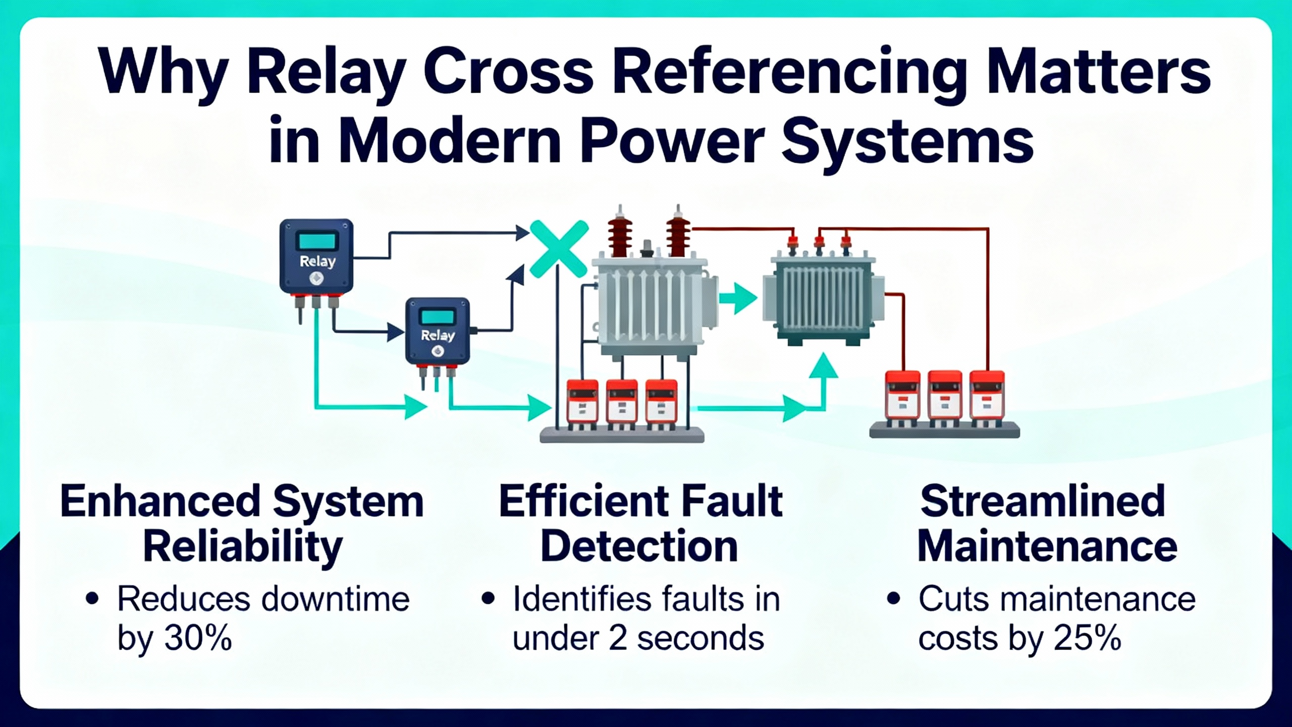
Why GE Relay Cross Referencing Matters in Modern Power Systems
In industrial and commercial power systems, relays are often treated as inexpensive commodities compared with switchgear, UPS modules, or inverters. Yet in reliability investigations, it is rarely the expensive assets that quietly undermine uptime; it is the small, aging relay that no one could find a proper replacement for. General Electric equipment in particular has a long legacy in low-voltage lighting, control, and protection, which means many facilities still depend on GE relays or GE-based designs that are decades old.
From vintage GE low-voltage lighting panels using RR series relays, to control relays between PLCs and contactors, to protective relays in feeders and tie-breakers, cross referencing a failed or obsolete GE relay is not just a part-number puzzle. Done well, it is a risk-control task that protects personnel, highŌĆævalue equipment, and operating uptime.
Industry guidance from sources such as Rockwell Automation, GE relay selection guides circulated by specialist suppliers, and relay selection notes from component distributors all converge on a simple point. When you substitute a relay, even for something as mundane as an interposing device, you must treat it as a small engineering project, not a oneŌĆæline purchasing exercise. The rest of this guide walks through how to do that safely and systematically in GE-based systems.
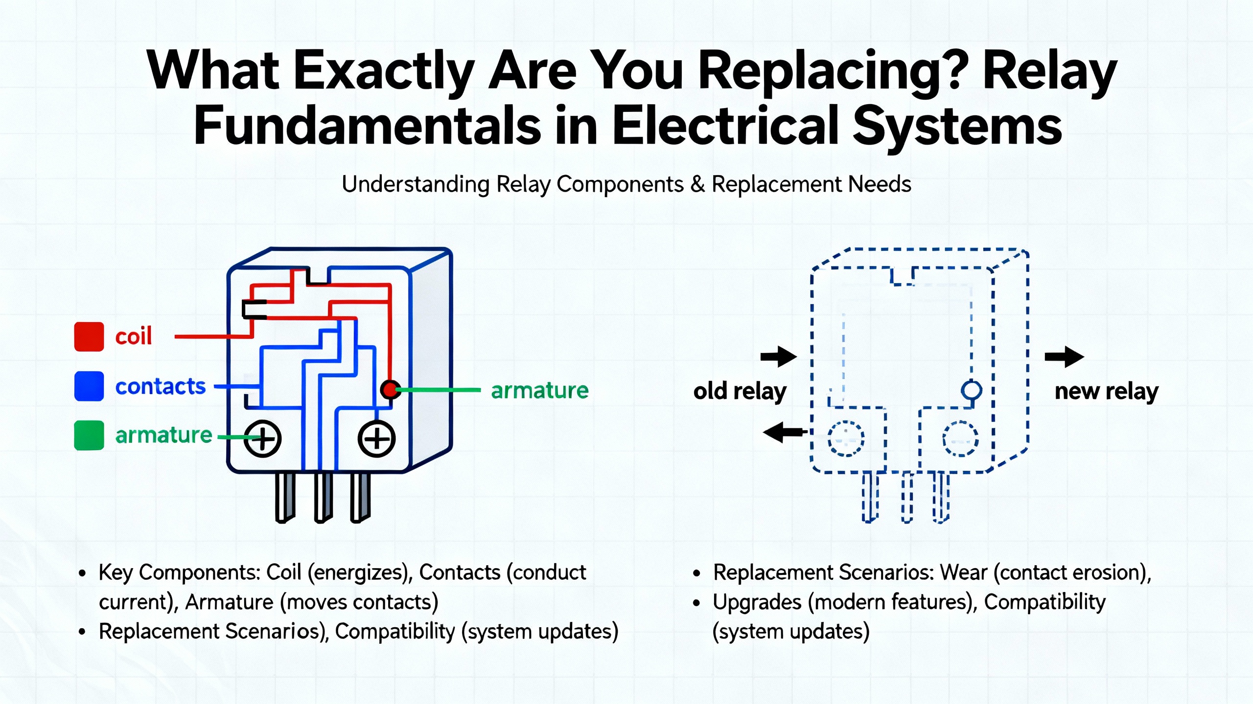
What Exactly Are You Replacing? Relay Fundamentals in GE Systems
A relay is an electrically controlled switch. A lowŌĆæpower coil circuit energizes an electromagnet (or a semiconductor in a solidŌĆæstate design) that opens or closes one or more higherŌĆæpower contact circuits. In the GE ecosystem, you will encounter three broad categories.
The first category is low-voltage control and lighting relays. Classic examples are GEŌĆÖs threeŌĆæwire and fourŌĆæwire lowŌĆævoltage lighting relays used with 24 VAC control circuits. In those systems, momentary wall switches send short on and off pulses to remote RR series relays that actually switch 120 V or 277 V lighting loads. A troubleshooting guide from a GEŌĆæfocused lighting supplier describes how a 24 VAC transformer feeds many coils, and how each relay coil draws roughly 220 mA when pulsed. The same guidance explains that individual wall switches typically command an associated relay, with threeŌĆæwire relays for simple on/off and fourŌĆæwire relays adding a pilotŌĆælight lead.
The second category is industrial control relays. These are the devices you find on DIN rails and printed circuit boards between PLC outputs and larger contactors or loads. A DigiŌĆæKey beginnerŌĆÖs guide points out that such control relays are sold as families with coordinated sockets, suppression modules, and jumpers. They might be switching lowŌĆæenergy ŌĆ£dry contactsŌĆØ or moderate power loads, but their main job is interposing and isolation: allowing lowŌĆævoltage control logic to safely operate higher voltages or currents.
The third category is protective relays. These devices supervise current, voltage, frequency, and other quantities and trip breakers when they detect faults. A relay replacement brief derived from GE and independent protective relay guidance describes how these units protect feeders, transformers, motors, and generators. They are not just switches; they embed protection curves, logic, and sometimes communication protocols. Cross referencing them affects system coordination and safety far beyond a single panel.
The first step in any GE relay replacement is to understand which of these roles you are dealing with, because the depth of analysis you need depends directly on the function the relay performs.
Before You Cross Reference: Identify the Existing GE Relay
Rockwell AutomationŌĆÖs guidance on cross referencing obsolete or unidentified relays starts with a simple mandate: do not guess. Before you even search a catalog, you need a clean identification of the existing relay and its context in the circuit.
At a minimum, you should capture four groups of data. First is the coil information: nominal coil voltage, AC or DC type, and any information about builtŌĆæin suppression devices. Component selection notes from DigiŌĆæKey and other distributors consistently emphasize that coil voltage is the primary search filter. For example, a forum case around a ŌĆ£dry contactŌĆØ circuit driven from 220 VAC quickly narrowed to a specific signal relay family once coil voltage and type were known.
Second is contact configuration. You need to know how many poles the relay has, whether contacts are normally open, normally closed, or changeover, and what current and voltage they are switching. One component specialist uses 2 A of switched current as a rough dividing line between signal relays and power relays, with GEŌĆæstyle ŌĆ£dry contactŌĆØ circuits usually falling into the signal category.
Third is mechanical form factor. In GE lowŌĆævoltage lighting systems, relays plug into specific panel positions and match certain wiring patterns. In control panels you will see PCBŌĆæmount relays, panelŌĆæmount cubes, and DINŌĆærail blocks. Distributors highlight matched relay families where the relay, socket, and surge suppressor are designed to work together. This is especially important when you replace a GE relay embedded in a socketed panel, because the replacement must either fit the existing socket or be supplied with a new one and rewired.
Fourth is the functional context. A relay used as an interposing device on a PLC output has different performance and safety expectations from a relay that is part of an automatic transfer scheme for a critical UPS. Protective relay replacement guidance stresses that you need an accurate oneŌĆæline diagram and a clear understanding of what the relay is protecting before you decide whether a ŌĆ£formŌĆæfitŌĆæfunctionŌĆØ replacement is acceptable or whether you need a functional upgrade.
A Simple Identification Table
The following table summarizes the core parameters you should document before you search for a compatible replacement.
| Parameter group | Why it matters in cross referencing | Example insight from references |
| Coil voltage and type | Ensures the coil will energize reliably without overstressing the driver | Component guides treat coil voltage as the key search filter |
| Coil suppression | Affects driver stress and polarity; critical for PLC and transistor outputs | Industrial control notes call diodes ŌĆ£effectively mandatoryŌĆØ for PLCs |
| Contact configuration | Determines whether the new relay can reproduce the control logic | Selection guides emphasize SPDT vs DPDT and N.O./N.C. contacts |
| Load rating and type | Protects contacts from overheating and arcing | Sources distinguish signal vs power relays around 2 A switching |
| Mechanical form factor | Avoids physical misfits and unsafe wiring ŌĆ£adaptationsŌĆØ | GE lighting guides show strict panel and strap compatibility |
If you cannot capture these elements from the nameplate alone, Rockwell Automation recommends using vendor datasheets and official support channels rather than improvising substitutions, especially in safetyŌĆærelated or highŌĆæload circuits.
Matching Electrical Performance: Coil, Contacts, and Load
Once you know what you have, you can begin to match what you need. In crossŌĆæreferencing work, the coil is where many hidden problems originate.
On an electrical engineering forum, a novice tried to replace a lowŌĆævoltage relay whose coil measured about 5 ohms with a candidate device whose coil measured 2,350 ohms. The voltages appeared similar, the form factor was close, and the contacts seemed adequate, but the coil resistance difference was enormous. Coil resistance directly sets the current at a given drive voltage; a relay designed to pull in at several hundred milliamps will not energize reliably if you substitute something that draws only a few milliamps under the same conditions. That case illustrates why it is not enough to match only coil voltage and contact current; you need to stay in the same ballpark of coil power.
In GEŌĆÖs vintage lowŌĆævoltage lighting systems, field troubleshooting guidance notes that each relay coil draws roughly 220 mA from a 24 VAC transformer during an on or off pulse. System-level recommendations caution against driving more than about five relays simultaneously from one transformer and against controlling more than eight relays from a single wall switch. When you cross reference an RR series relay in these panels, you must therefore consider not only whether the replacement coil will energize, but whether it will overload or underload the existing transformer and control wiring.
Contact ratings are the second critical dimension. Relay selection guides from industrial suppliers describe three main relay types. Electromechanical relays with a coil and mechanical contacts tolerate a wide range of voltages and currents, including higher surge currents, at the cost of slower operation and finite mechanical life. Reed relays in sealed glass capsules are faster and have excellent isolation but are more sensitive to contact arcing. Solid-state relays switch through semiconductors and have no moving parts, making them attractive for very high switching frequencies but more vulnerable to surge currents and requiring careful thermal design.
When you replace a GE power relay with a solid-state device, you may gain life and speed, but you must check surge current ratings and load type carefully, especially for inductive loads such as motors, solenoids, and transformer primaries. Sources focused on energyŌĆæefficient systems note that optimizing relay selection can materially improve overall efficiency, including in EV charging and solarŌĆæpowered HVAC applications, but only if contact ratings and load types are correctly matched to avoid overheating or early failure.
Finally, you need to consider the environment. Industrial relay selection articles highlight temperature, humidity, dust, vibration, and corrosive agents as major factors. In harsh manufacturing, oil and gas, or mining environments, relays with sealed enclosures, robust plastics, and corrosionŌĆæresistant metals are preferred. In GE lowŌĆævoltage lighting panels in older buildings, you commonly see relays and switches exposed to dust, grease, or paint, and the troubleshooting guides link these conditions directly to stuck buttons and overheated coils.
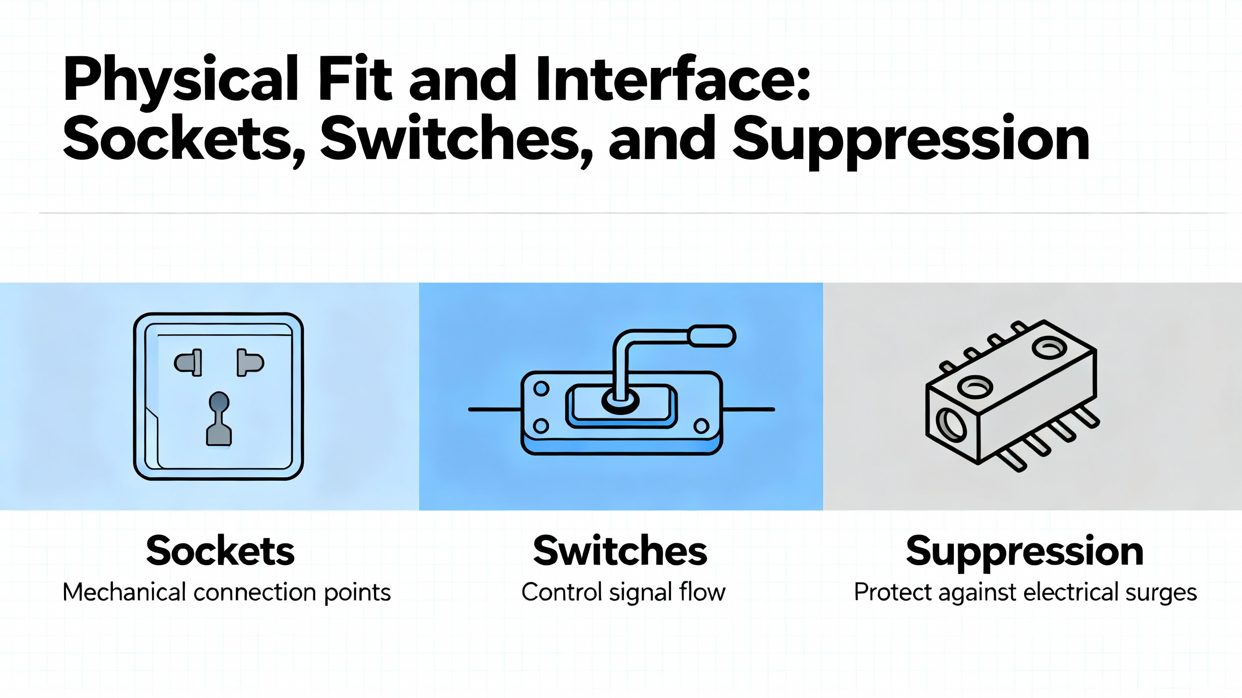
Physical Fit and Interface: Sockets, Switches, and Suppression
Even when the electrical parameters line up, physical details can make or break a replacement.
In GE lowŌĆævoltage lighting systems, one switch and relay supplier explains that modern replacement switches are physically larger than the originals and use two square push buttons for on and off. If someone forces these newer switches into the older rectangular metal straps, the mechanism can bind. The buttons may not fully release, leaving the 24 VAC coil energized for long periods and eventually burning out the associated relay. The same source recommends replacing the cover plate and any adjacent switches when upgrading to modern parts, and using updated snapŌĆæin plates that accept the new switch geometry without strain.
The relay side has similar physical nuances. In RR7 and RR9 replacement relays, brass screws and bottom wiring holes are laid out so that breaker feeds and lamp loads enter specific numbered terminals. MultiŌĆærelay arrangements often share a breaker feed using jumpers between designated holes. When you substitute a relay, even with a GEŌĆæbranded replacement, you must match these connections carefully to avoid mis-wiring that defeats overcurrent protection or leaves loads permanently energized.
On the control-relay side, industrial control relay families such as those described by DigiŌĆæKey include matched sockets, surge suppression modules, and markers. A common practice in PLC panels is to use these as interposing relays so that a 24 VDC PLC output drives the relay coil, which in turn switches a higher or different voltage to a contactor or other device. In DC systems, the suppression module is not optional. The same DigiŌĆæKey guidance notes that freewheeling diodes across each DC coil are effectively mandatory to clamp the voltage spike generated when the coil is turned off; otherwise, the backŌĆæEMF can damage solidŌĆæstate outputs.
A separate hobbyist discussion around automotive relays raised the question of why some coils have diodes, others resistors, and others no builtŌĆæin suppression at all. The principle is the same: when you open current through an inductive coil, the stored energy tries to keep the current flowing, producing a voltage spike. A diode provides very effective clamping for semiconductor drivers, but slows the coilŌĆÖs release slightly; a resistor dissipates the energy more gradually with a higher residual voltage. In any GE panel where PLC outputs or transistor drivers control relays, changing from a coil without a diode to one with a builtŌĆæin diode, or changing polarity relative to the diodeŌĆÖs orientation, can be the difference between a reliable upgrade and a blown output module.
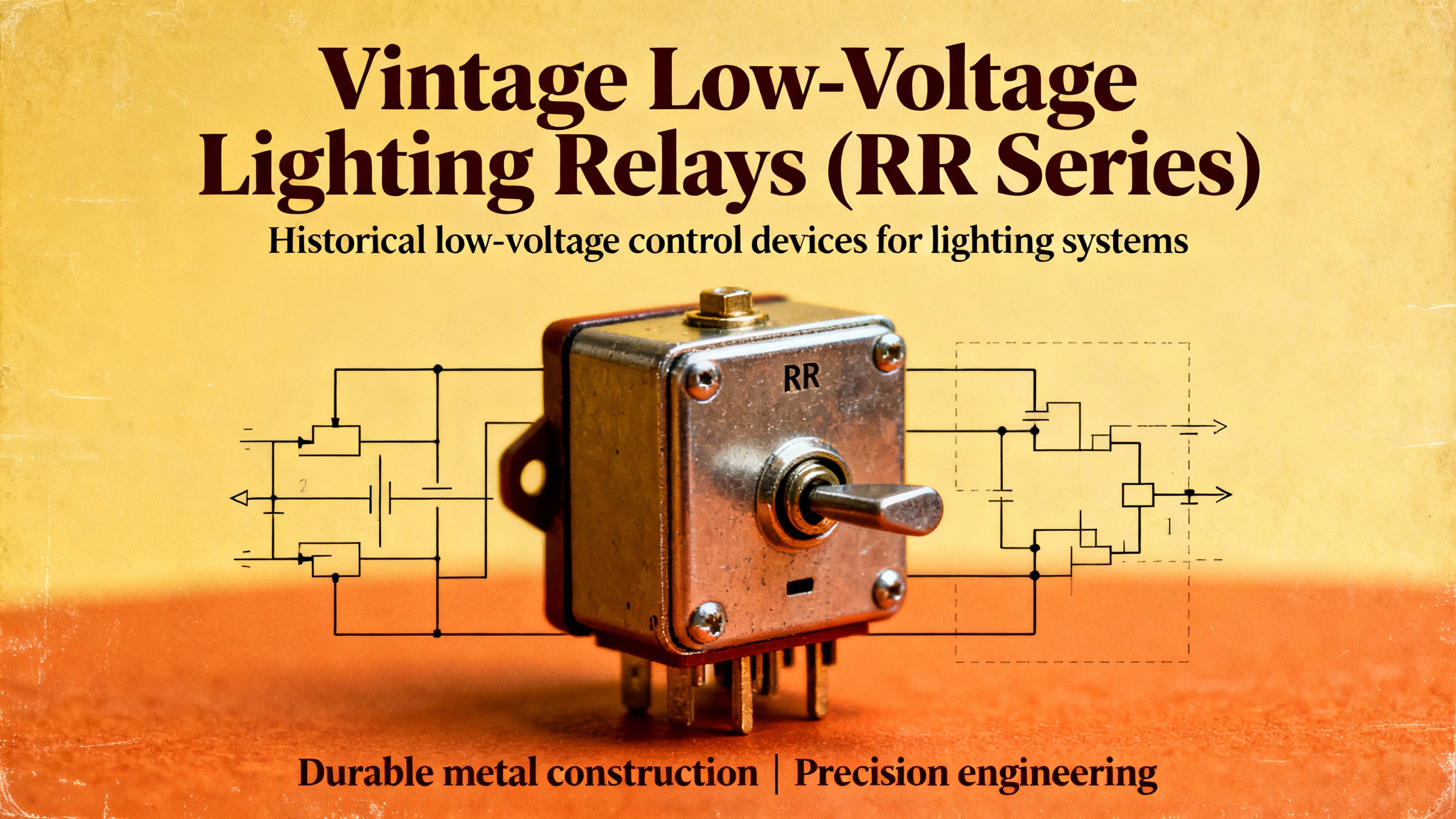
Special Case: Vintage GE Low-Voltage Lighting Relays (RR Series)
Vintage GE lowŌĆævoltage threeŌĆæwire lighting systems deserve their own section because the crossŌĆæreference rules are relatively well documented and the failure modes are deceptively simple.
A replacement and troubleshooting guide focused on these systems provides a clear, practical mapping. Older threeŌĆæwire relays labeled RR2, RR3, or RR5 are replaced with an RR7 relay. Older fourŌĆæwire relays with a pilotŌĆælight lead, often yellow, labeled RR4, RR6, or RR8 are replaced with an RR9 pilotŌĆælight relay. When installing an RR7 in place of an older threeŌĆæwire relay, the rule is to match red control wires to the new red lead, black control wires to the new black lead, and the former common control lead (often white) to the new blue wire that ties into the system rectifier or control circuit. RR9 pilotŌĆælight versions add the yellow pilot conductor to an extra switch terminal.
These systems run from a 24 VAC transformer feeding many relays. Troubleshooting recommendations call for verifying that the blue lead has 24 VAC available, then briefly shorting the red lead to common to command on and the black lead to common to command off, listening for clicks and checking lineŌĆævoltage continuity. A good relay reads about 120 V across the brass screws when off, dropping to about 0 V when on. A loud buzzing relay is typically a sign of a faulty relay or a stuck switch that is holding the coil partially energized.
One practical recommendation stands out. When you replace a failed lighting relay, it is wise to replace all older switches tied to that relay, including any master panel switches. The reasoning is simple: worn or slow momentary switches and misaligned or paintedŌĆæover wall plates tend to hold the common contact closed too long. That overheats the relay coil and transformer and is a primary cause of repeat failures. The same source notes that a single transformer can feed dozens of relays, but you should avoid driving more than about five at the same instant, and that GE historically advised against controlling more than eight relays from one switch. Where larger groups are needed, sequenced systems that send short pulses to each relay in turn are recommended.
If your devices or plates do not match the documented GE parts, the guidance is to confirm whether the system is actually GE or another brand such as Pyramid, Sierra, Touch Plate, or Remcon, before buying replacements. That is a crossŌĆæreference step in itself: misidentifying the vintage lowŌĆævoltage system brand is a common and costly mistake in renovations.
Protective Relays and OT Modernization: When ŌĆ£Drop-InŌĆØ Is Not Enough
Protective relays are the brains behind breakers in switchgear and critical power systems. They monitor conditions such as current, voltage, and frequency, and issue trip signals during faults. A protective relay replacement guide based on GE and general industry practices describes how replacement is driven less by immediate failure and more by obsolescence, lack of manufacturer support, misoperations, and new coordination or compliance requirements.
In these cases, cross referencing a GE protective relay is not simply a matter of matching coil voltage and contacts. You must ensure that the new device provides equivalent or better protection functions, works with the existing current and voltage transformers, and supports the necessary communication and event recording features. That same guidance advocates starting with an inventory of existing relays by type, location, function, age, and support status, then prioritizing replacements based on criticality and misoperation history rather than age alone.
Rockwell Automation connects relay cross referencing to a wider operational technology (OT) modernization story. In a case study with a major oil and gas producer, they describe how better asset and component management helped reduce OT security labor costs by about 70 percent while improving visibility across operations and reducing risk. The lesson for relay work is straightforward. You should treat protective relays as managed assets with lifeŌĆæcycle plans and complete records, including their GE model numbers, settings, firmware, and locations. That makes future replacements more predictable and less dependent on whoever happens to be on site when a relay fails.
GEŌĆÖs own relay selection and replacement material, as summarized by specialist suppliers, typically provides families of protective relays and maps them to feeders, transformers, motors, and generators. Those selection tables, along with crossŌĆæreference catalogs and official support portals, are the right starting point whenever you are replacing an older GE protective relay with a modern equivalent.
Using Cross-Reference Tools and Vendor Data Without Losing Control
Today, engineers and technicians have many tools at their disposal for finding a ŌĆ£compatibleŌĆØ relay. Distributors offer keyword search, parameter filters, and associatedŌĆæproduct links. TE Connectivity, for example, provides a relay selector tool that proposes products based on user input. At the same time, TE explicitly states that the toolŌĆÖs outputs are not product recommendations, not guaranteed errorŌĆæfree, and provided strictly asŌĆæis. They disclaim any implied warranties of merchantability or fitness for a particular purpose and assign all verification responsibility to the user.
This legal language aligns with the engineering reality. You can use selector tools and crossŌĆæreference charts as a starting point to see which relays might match a given GE part, but you must verify everything against datasheets and the actual application. Rockwell AutomationŌĆÖs support note on cross referencing relays and NPEIncŌĆÖs guidance on decoding GE breaker model numbers both stress that every character in a model number can encode significant differences in ratings, options, and compatibility. Two parts that look almost identical can still be incompatible in shortŌĆæcircuit rating, mechanical fit, or trip function.
Forum discussions about substitution, such as one focused on replacing a relay with a lowŌĆæcost HSINDA 943ŌĆæ1CŌĆæ24DS unit from a commodity distributor, reinforce the same point. Low unit price is attractive, but without matching coil voltage, contact configuration, current and voltage ratings, and PCB footprint or socket pinout to the original part, you are taking an avoidable risk with your equipment.
A practical way to keep control is to treat the selector toolŌĆÖs result as a candidate set, then build a short justification note for the chosen replacement. That note should show how each critical parameter from your identification step is satisfied by the new part. In a highŌĆæreliability environment, such as UPS and inverter systems serving critical loads, that justification becomes part of your maintenance and OT documentation.
Common Pitfalls When Substituting GE Relays
Patterns from troubleshooting guides, forum cases, and vendor notes reveal recurring mistakes in relay cross referencing.
One widespread issue is relying on vague language like ŌĆ£dry contactŌĆØ without hard numbers. A DigiŌĆæKey support discussion notes that ŌĆ£dry contactŌĆØ simply indicates a lowŌĆæenergy contact that is not internally powered; it does not specify currents, voltages, or even whether the relay is driving or being driven by the contact. When someone tries to select a relay based only on ŌĆ£dry contact,ŌĆØ they may end up with a device that cannot reliably switch the actual energy in the circuit.
Another problem is neglecting coil suppression and polarity. As controlŌĆærelay guides emphasize, DC relay coils driven by PLCs or solidŌĆæstate outputs require suppression diodes or modules across the coil. When you cross reference a GE relay with no internal diode to one that has a builtŌĆæin diode, you must wire the coil with the correct polarity and confirm that the driver expects a diode to be present. If you fail to do so, you can either expose the driver to damaging voltage spikes or short the supply through a misoriented diode.
Mechanical fit mistakes show up frequently in GE lowŌĆævoltage lighting systems. Forcing modern twoŌĆæbutton switches into old straps, painting or wallpapering over wall plates so that buttons cannot move freely, or mixing switch types can all result in stuck contacts. The troubleshooting guide for these systems ties such mechanical problems directly to overheated coils, buzzing relays, and transformers dropping into thermal protection as they struggle under continuous loads they were never designed to handle.
Finally, there is the temptation to oversimplify protective relay replacement. Guidance for protective relay programs points out that older electromechanical relays can function for several decades with maintenance, while digital relays are often refreshed on shorter technology cycles to keep up with new features and security expectations. Trying to ŌĆ£drop inŌĆØ an unrelated relay simply because it shares a GE logo and similar case size risks undermining your coordination and faultŌĆæclearing performance.
In my experience working with powerŌĆæquality and protection issues in UPS and distribution systems, most relayŌĆærelated incidents trace back to these same themes: incomplete identification, overreliance on catalog similarity, and underestimation of the protection functionŌĆÖs significance. A disciplined crossŌĆæreference process is not overkill; it is cheap insurance.
Short FAQ
Can I replace an obsolete GE relay with any relay that has the same voltage and current ratings?
No. Matching nominal voltage and current is only the starting point. You also need to match coil type and power, contact configuration, load type, mechanical form, and suppression details. Rockwell AutomationŌĆÖs guidance explicitly lists coil voltage, contact configuration, contact load ratings, and physical form factor or socket type as minimum requirements for functional equivalence. For protective relays, you must also match protection functions and integration with current and voltage transformers.
How should I cross reference a GE RR2 or RR4 lighting relay?
Guidance from a GEŌĆæfocused lowŌĆævoltage lighting supplier indicates that older threeŌĆæwire relays labeled RR2, RR3, or RR5 are replaced with an RR7 relay, while fourŌĆæwire relays with a pilotŌĆælight lead labeled RR4, RR6, or RR8 are replaced with an RR9 pilotŌĆælight relay. When doing so, follow the documented wiring conventions for red, black, white or common, blue, and yellow leads, and inspect the associated switches and wall plates for mechanical issues that could have contributed to the original relayŌĆÖs failure.
When should I call the OEM or a specialist instead of handling the cross reference inŌĆæhouse?
If the relay is part of a protection scheme for feeders, transformers, generators, or critical UPS tie breakers, or if the part number is incomplete or heavily modified, it is prudent to involve GE, a qualified relay engineer, or a specialist supplier. Rockwell AutomationŌĆÖs support note recommends using official support portals and crossŌĆæreference catalogs rather than ad hoc substitutions in safetyŌĆærelated applications. Similarly, when a relay appears in a complex GE system with encoded model numbers and options, such as legacy breakers and their accessories, decoding those numbers correctly often requires specialized reference material.
Closing
Cross referencing GE relays is ultimately about preserving the intent of the original design while adapting to todayŌĆÖs parts, tools, and reliability expectations. If you treat every relay substitution as an engineered decision, anchored in clear identification, disciplined parameter matching, and respect for the protection function, you will find that even small components can contribute to a robust, modernized power system rather than becoming its weakest link.
References
- https://www.npeinc.com/how-to-find-and-identify-old-or-obsolete-ge-general-electric-circuit-breakers-type-ak-and-akr
- https://www.ry-elerelay.com/a-how-to-choose-a-relay-key-factors-tips-explained.html
- https://www.justanswer.com/electrical/35736-replacement-low-voltage-relays-1-3h-p-125v.html
- https://www.kyleswitchplates.com/ge-low-voltage-troubleshooting-tips/?srsltid=AfmBOop8owVLDET-30exwm4BXDlnJrYu_NMrf9fmtwkrunxlcDGd6LeX
- https://simcona.com/blog/relay-selection-guide
- http://kyleswitchplates.blogspot.com/2018/08/how-to-replace-low-voltage-ge-switch.html
- https://forum.digikey.com/t/beginners-guide-to-selecting-an-industrial-control-relay/35669
- https://www.electro-tech-online.com/threads/help-choosing-a-replacement-relay.163174/
- https://www.hirelays.com/blog/essential-tips-for-selecting-electric-relays/
- https://forums.mikeholt.com/threads/identify-a-relay.149884/


 Videos
 News
News Applications


Leave Your Comment