Why Contactor Wiring Diagrams Matter In Critical Power Systems
In industrial and commercial power systems, contactors sit right at the fault line between safe, reliable operation and expensive downtime. In UPS input and bypass cabinets, inverter output switchgear, and generator tie panels, a single miswired contactor can keep an entire critical bus from transferring, leave a UPS stranded on battery, or create a dangerous backfeed path.
Across the wiring and blueprint guidance from sources such as Alpha Omega Electric, Development Electric, Nash Electric, and Anytime Electric, one theme is consistent: safe, wellŌĆæplanned wiring starts on paper with accurate drawings and ends in the field with disciplined installation and inspection. Residential and commercial wiring articles stress that proper load calculations, correctly sized conductors, and codeŌĆæcompliant installation are essential for preventing shocks, fires, and nuisance trips. Industrial control panel guidance from Simcona extends the same principle to complex equipment, emphasizing that panel layouts and wiring need to support both immediate performance and longŌĆæterm maintainability.
CADDrafterŌĆÖs overview of electrical drawings notes that roughly a third of construction rework can be traced to documentation errors, adding around ten percent to project cost. When the equipment in question includes UPS input contactors, bypass contactors, transfer switch mechanisms, and motor starters, those errors are not just costly; they can compromise power quality and uptime for entire facilities.
In my own reliability reviews of existing UPS and power distribution systems, unclear or outdated contactor wiring diagrams are one of the fastest ways to stall a troubleshooting effort. Technicians end up chasing wires across multiple pages, guessing at interlocks, and manually tracing circuits that should have been obvious from the documentation. That is precisely the risk the standards and best practices below are designed to avoid.
A simple example makes this concrete. Imagine a maintenance bypass contactor in a UPS lineup that fails to pull in when commanded. If the diagram clearly shows the control power source, every series permissive contact, and the coil terminals, a technician can check each path in minutes. If the diagram is incomplete or inconsistent with the panel, you lose hours tracking down the same information with a meter and a flashlight. In a facility where downtime is measured in thousands of dollars per minute, that documentation quality is a reliability issue, not a cosmetic one.
Diagram Types And Where Contactors Fit
Many sources, including TestGuyŌĆÖs overview of electrical drawings and SkillCatŌĆÖs guide to electrical blueprints and wiring diagrams, emphasize that no single drawing can convey everything about a system. Instead, you use several diagram types together. For contactors, this distinction is critical.
TestGuy explains that singleŌĆæline diagrams summarize power distribution, while threeŌĆæline diagrams expand the phase detail. Schematics show how components are functionally connected, and wiring diagrams show the physical locations, terminal numbers, and wire tags used for installation and maintenance. SkillCat reinforces that wiring diagrams focus on how conductors are actually connected between components and that technicians must be comfortable tracing circuits across multiple pages.
In a UPS or inverter installation, you will typically see contactors represented in all of these forms. A singleŌĆæline drawing might show only a symbol for a maintenance bypass contactor in series with the UPS output. A schematic diagram shows the coil, its auxiliary contacts, interlocks with other devices, and any protective devices in the control circuit. A wiring diagram shows the same contactor with its actual terminal numbers, wire identifiers, and routing to terminal blocks and field devices.
The table below summarizes how different diagram types describe contactors in a critical power project.
| Diagram type | What it shows about contactors | How it is used around UPS and inverters |
| SingleŌĆæline | Simplified symbol for the contactor in the power path, often without coil details | Used in early design, load studies, and as an operator reference to understand normal and bypass paths |
| Schematic | Functional view of coil, main contacts, auxiliaries, and interlocks in the deŌĆæenergized state, as TestGuy recommends | Used by engineers and technicians to understand logic, interlocks, and sequencing for transfer and protection |
| Wiring diagram | Actual wire numbers, colors, device tags, and terminal designations, as described by SkillCat | Used for panel fabrication, field installation, and detailed troubleshooting at the terminal level |
| Block or logic diagram | HighŌĆælevel blocks for control logic, sometimes summarizing permissive chains | Used to communicate operating philosophy and control interactions without detailed wiring |
A realŌĆæworld example from heavy equipment and control systems illustrates how the right diagram type reduces confusion. An engineer on Electrical Engineering Stack Exchange described multiŌĆæpage wiring documentation for heavy machinery that was ŌĆ£extremely messy and hard to use,ŌĆØ forcing technicians to flip through many sheets to find key information. Practitioners in that discussion suggested separating schematic logic from physical wiring diagrams and organizing related functions clearly. Applying the same approach to contactors in a UPS lineŌĆæup means putting all of the coil logic, auxiliary contacts, and permissives on a small number of wellŌĆæorganized schematic pages, while leaving routing and harness details to wiring diagrams.

Standards And Conventions That Keep Contactor Diagrams Clear
Symbol And Layout Conventions
SkillCat and TestGuy both stress the importance of standardized symbols and line types. Standardized contactor symbols make it possible for technicians to instantly recognize the difference between a main power contact set and auxiliary contacts, and to follow how they interact with relays, switches, and protective devices.
TestGuy notes that schematics should be drawn with switches and contacts in the deŌĆæenergized state. That convention matters for contactor diagrams, because it defines how normally open and normally closed auxiliary contacts are shown relative to a coil. When the coil is deŌĆæenergized, a normally open auxiliary contact is drawn open, and a normally closed auxiliary contact is drawn closed. Maintaining that convention across an entire project prevents misunderstandings during commissioning or fault finding.
Clarity is also a layout problem. The Arduino community discussion about schematic readability recommends making electrical symmetries appear visually symmetrical and redrawing circuits several times by hand before committing them to CAD. That advice maps directly to contactor schematics: keep the coil and its main associated contacts aligned, group related interlocks nearby, and avoid long crossŌĆæpage jumps where possible. When I review control drawings, I look for whether each contactorŌĆÖs coil and key auxiliary contacts can be understood at a glance. If not, the diagram is doing the technician no favors.
Tools matter as well. TPC TrainingŌĆÖs guidance on drawing electrical diagrams highlights the advantages of modern schematic software: robust symbol libraries, templates, and the ability to update and reŌĆæexport drawings quickly. CADDrafter notes the shift from paper to digital blueprints, where electronic formats allow instant updates and easier coordination. For critical power systems with frequent change orders and retrofit work, this ability to maintain the ŌĆ£single source of truthŌĆØ is essential.
Wiring And Routing Conventions
On the physical wiring side, SimconaŌĆÖs control panel layout recommendations and Nash ElectricŌĆÖs commercial wiring best practices provide concrete guidance that applies to contactor circuits just as much as to any other industrial wiring.
Simcona advises grouping components by current type, heat, and function: separating AC and DC sections, keeping heatŌĆæproducing devices near airflow, and clustering similar devices such as contactors and relays. They also recommend routing wires horizontally and vertically rather than diagonally, using ducts or trays instead of simple ties, and separating sensitive control or communication cables from highŌĆæpower conductors. Nash ElectricŌĆÖs commercial wiring guidance reinforces the need to use conduit and structured cable management, especially where wiring is exposed to moisture, mechanical damage, or interference.
Taken together, these recommendations mean that contactors should not be an afterthought squeezed into any spare space. Their power and control wiring should follow the same disciplined routing as the rest of the panel. This is not only about aesthetics. Clean routing reduces the chance of accidental shorts, makes fault tracing faster, and improves airflow around heatŌĆæproducing components.
Simcona also highlights the importance of maintaining appropriate clearances, referencing NEC and UL requirements, and suggests reserving roughly twenty percent of enclosure space as spare capacity for future modifications. In a UPS or inverter panel, that reserved space is the difference between cleanly adding a future bypass contactor or generator tie and having to rebuild the entire enclosure.
A simple planning calculation shows why this matters. If you design a control panel that is completely full on day one, any future contactor addition will require either a second enclosure or major rework. That rework is precisely the kind of cost and schedule hit that CADDrafter links to poor documentation and coordination. Designing for twenty percent spare space is a small cost upfront that significantly reduces the risk of disruptive changes later.
Documentation And Revision Conventions
Drawings become unreliable as soon as they stop matching the asŌĆæbuilt installation. TestGuyŌĆÖs discussion of asŌĆæbuilt drawings makes clear that final documentation must reflect the exact, completed project and every modification, even minor ones. The Mike Holt forum thread on representing revised wiring diagrams raises a practical question: how do you communicate what is being demolished and what is new when revising terminal block wiring in control cabinets?
Practitioners suggest keeping the original diagram available, marking conductors to be removed, and then providing revised drawings that show the new wiring clearly. In parallel, the Arduino forum discussion on schematic creation emphasizes disciplined version control, recommending that designers save schematics with incrementing numbers so they can roll back from errors.
For contactor wiring, the combination of these ideas leads to a simple standard: maintain a clear revision history in the title block of each drawing set, keep previous versions accessible, and document terminalŌĆæbyŌĆæterminal changes when you rewire or replace contactors. When I review critical power systems, I pay close attention to whether panel door diagrams match the actual wiring. If a technician cannot trust the drawing, they will revert to adŌĆæhoc tracing, and every subsequent change becomes riskier.
Electrical Connection Best Practices For Contactor Circuits
Conductor Selection And Protection For Contactor Circuits
Across multiple sources, the message is consistent: use appropriate, highŌĆæquality conductors, and ensure that overcurrent protection is properly matched.
Nash Electric highlights that copper wiring is preferred for most commercial applications because of its conductivity, durability, and heat resistance, while aluminum is sometimes chosen for highŌĆævoltage applications due to cost and weight but requires extra care to avoid oxidation and loosening over time. Residential and small commercial guidance from Anytime Electric, Sunny the Penguin, and Constellation underscores that conductor size must match circuit rating. SunnyŌĆÖs guide notes that 14ŌĆægauge copper is commonly used for circuits up to 15 amps, and 12ŌĆægauge copper for 20ŌĆæamp circuits. ConstellationŌĆÖs home safety tips mention that a 16ŌĆægauge cord is rated for about 1,375 watts at 120 volts, illustrating the principle that smaller gauge conductors can safely carry substantial power when properly protected.
These same principles apply to contactor circuits. The contactorŌĆÖs main power path must be wired with conductors sized for the load current and breaker rating, following the same loadŌĆæcalculation practices recommended by Anytime Electric and Development Electric. Those sources advise formal load calculations for new residential and commercial installations so that wires, circuits, and panel capacity are correctly sized and circuits are not overloaded. In a UPS input or bypass feeder, that means ensuring that the contactor, its downstream conductors, and the protective device are all aligned with the calculated load, with appropriate margin.
For control circuits that energize contactor coils, the current is much lower than for power circuits, but you still want mechanically robust, appropriately rated conductors. Guidance from Nash Electric about voltageŌĆæspecific wiring and from SkillCat about correctly identifying wire types and voltage levels applies here: use wiring rated for the control voltage and environment, and clearly distinguish it from power conductors, especially when DC control power is present alongside AC mains.
An example helps tie these ideas together. Suppose you have a UPS maintenance bypass contactor on a branch that supplies several racks of IT equipment. If that load is similar in magnitude to a fully utilized 20ŌĆæamp branch circuit, then following the residential and commercial guidance, you would ensure that the conductors and protective devices match or exceed that rating. That alignment means that the contactor, wiring, and breaker all have a consistent margin against overload, reducing both thermal stress and nuisance trips.
Physical Routing, Segregation, And Panel Layout
Routing and layout are where standards from Simcona, Nash Electric, and NFPAŌĆæstyle guidance converge with dayŌĆætoŌĆæday reliability concerns.
SimconaŌĆÖs recommendations for control panel layout include separating AC and DC sections, keeping highŌĆæpower ŌĆ£bad actorsŌĆØ away from sensitive circuits, and using trays or ducts instead of simple wire ties. They advise routing wires only horizontally or vertically and using service loops and slack at cable entry and exit points so that wires can be moved or reterminated over a twentyŌĆæplusŌĆæyear panel life. They also recommend the use of cable trays and ducts to protect and organize conductors, and to keep sensitive communication cables away from highŌĆæpower wiring.
Nash Electric adds that commercial installations should avoid running conduit where it conflicts with plumbing or HVAC, should maintain accessibility for maintenance, and must follow National Electrical Code guidelines for conduit sizing, spacing, and materials. For network cabling, they recommend shielded twisted pair or fiber and physical separation from power conductors to protect against electromagnetic interference.
Applied to contactors, these practices translate into several concrete design and installation decisions. Keep the highŌĆæcurrent line and load conductors to each contactor in a wellŌĆædefined route, with clearances and bends that respect both conductor limits and enclosure space. Place contactors and their control terminals in areas where service loops can be tucked neatly into ducts rather than hanging across other components. Maintain physical separation between coil wiring and any sensitive analog or communication wiring. When you add a new contactor to an existing UPS or inverter cabinet, take the time to extend the existing routing standards rather than running the shortest possible path.
Simcona also recommends service loops and slack at cable entries, balanced so that there is enough extra length for future modifications but not so much that ducts overflow. This is especially important at contactor terminals, which are replaced more often than the surrounding enclosure. If a contactor fails after years in service, having adequate slack on its conductors allows you to replace it quickly without splicing in additional wire segments that complicate the layout.
A practical example from panel upgrades illustrates the benefit. In a control panel designed with generous service loops that comply with SimconaŌĆÖs recommendations, adding an auxiliary contact block for a new UPS monitoring function required nothing more than rerouting existing control wires. In an older panel without slack or duct capacity, the same change would have required splices, additional terminal blocks, and a disproportionate amount of labor. The difference traces back to routing and layout decisions made at the original design stage.
Terminations At Contactors: Coils, Power Poles, And Auxiliaries
Wire terminations are a common failure point in any electrical system. Family HandymanŌĆÖs detailed guidance on making safe wire connections emphasizes that loose connections cause arcing, tripped breakers, and electrical fires, and notes that poor splices and terminations are the first things to check when a circuit is not working. Performance WireŌĆÖs safety procedures add that improper or loose connections can ignite at any time and should be mechanically secure and electrically sound, with physical pull tests before walls are closed or trenches backfilled.
For contactors, this means that coil terminals, line and load lugs, and auxiliary contact terminations must all receive the same disciplined treatment. Family Handyman describes best practices for stripping insulation, aligning conductors, using twistŌĆæon connectors or pushŌĆæin connectors correctly, and making screwŌĆæterminal connections with solid and stranded conductors. They recommend stripping appropriate lengths of insulation using the correct groove on the stripper, avoiding nicks in the copper, twisting strands tightly where needed, and wrapping solid conductors clockwise around terminal screws so that tightening the screw tightens the connection rather than loosening it. Sunny the PenguinŌĆÖs wiring guide reinforces this with detailed steps for stripping between about half an inch and one inch of insulation, matching connectors to wire gauge, and confirming that no bare conductor extends beyond the terminal.
SimconaŌĆÖs discussion of ferrules adds another dimension for industrial panels. Ferrules on stranded conductors relieve strain, reduce contact resistance, and prevent strand splay under screw clamps, especially at frequently serviced components such as contactors. They recommend correctly sized ferrules, adequate termination space, and clear labeling printed on the ferrules themselves.
In practice, when wiring a contactor, I expect to see control wires terminated with ferrules at the coil and auxiliary contacts, power conductors correctly stripped and tightened under lugs, and every termination subjected to a firm tug test as recommended by Performance Wire and Family Handyman. If a conductor moves under moderate pull, it is not ready for service.
A simple test sequence might go like this. With power off and verified deŌĆæenergized using a voltage tester, as recommended by Performance Wire and Sunny, the technician makes each termination, then applies a firm pull. Once all connections inside the contactorŌĆÖs wiring zone are complete and tugŌĆætested, they close up the enclosure, restore power, and verify that the contactor operates correctly under load. Finally, they use a voltage tester again on external metalwork to confirm that no unintended energization of enclosures or conduit has occurred.

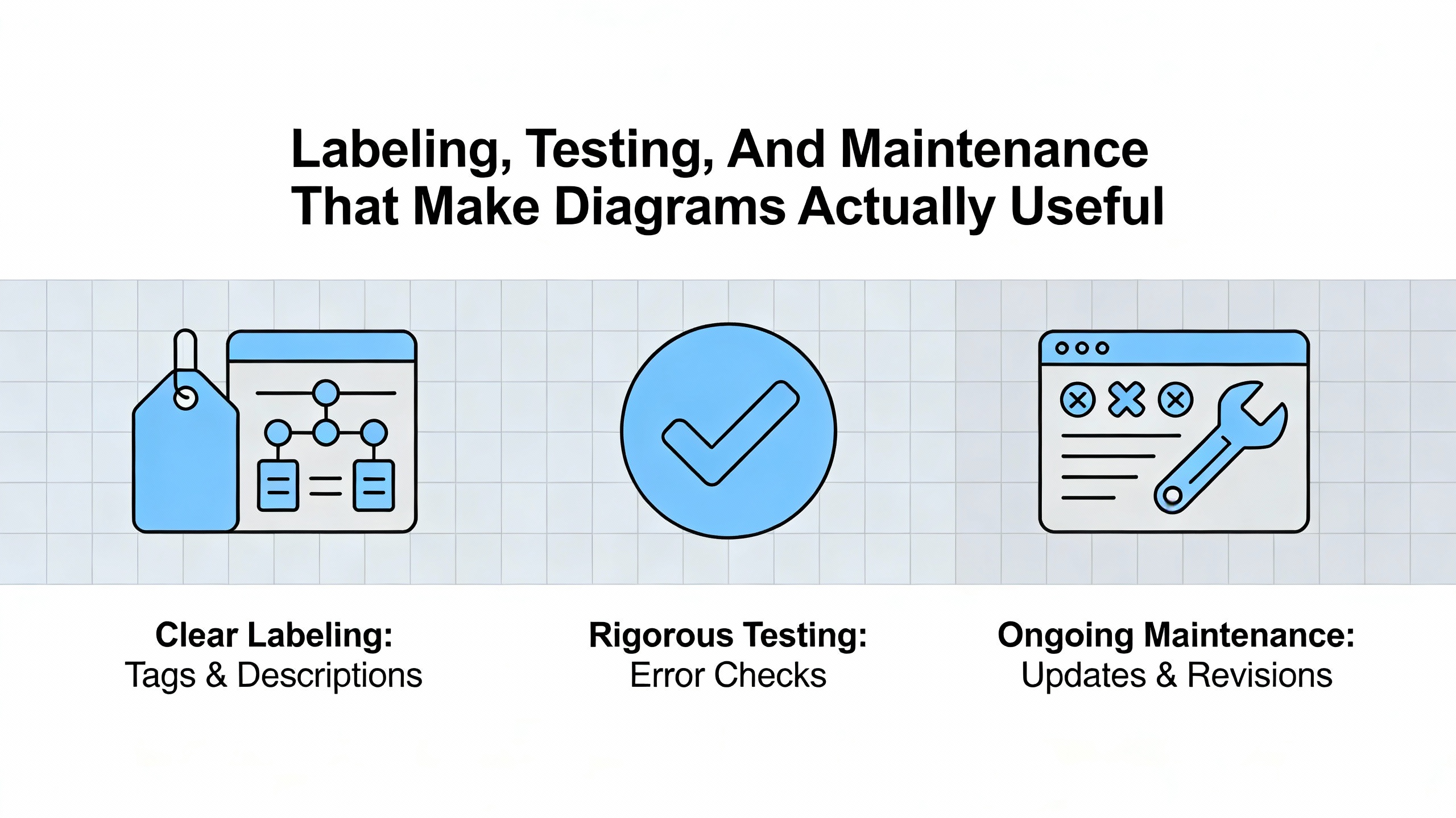
Labeling, Testing, And Maintenance That Make Diagrams Actually Useful
Labeling And Identification
Nash ElectricŌĆÖs commercial wiring best practices emphasize proper labeling and organization. They recommend marking each cable with its voltage rating, circuit number, and destination, and using standardized color coding to distinguish power, lighting, and data circuits. Simcona adds that ferrules can carry printed IDs and, combined with consistent color schemes, dramatically speed troubleshooting.
SkillCat and TestGuy both point out that technicians must be able to match symbols and labels on drawings with real hardware in the field, tracing wire numbers and color codes, and verifying that drawing revisions match what is installed. Schedules and panelboard tables, as described in TestGuyŌĆÖs overview, can list breaker ratings, feeder sizes, and the loads they serve, establishing an explicit link between schematic references and physical devices.
For contactors, this means that each device should have a device tag that appears consistently across singleŌĆæline diagrams, schematics, wiring diagrams, and panel labels. Likewise, coil terminals, auxiliary contacts, and associated terminal blocks should have wire numbers that align with the wiring diagram. When that discipline is in place, a technician can move from a UPS singleŌĆæline diagram showing a bypass contactor symbol to the schematic that describes its control logic, to the wiring diagram showing its terminal references, and finally to the physical panel, all without losing the thread.
A practical example from maintenance work: when a contactor fails to drop out on a transfer command, a technician can follow the wire number associated with the holding auxiliary contact from the wiring diagram through the panel to the device, then confirm its state with a meter. Without consistent labeling, that same operation involves trial and error in a crowded panel, significantly increasing the risk of mistakes.
Testing, Commissioning, And Ongoing Maintenance
Safety and reliability guidance from Performance Wire, Alpha Omega Electric, Sunny the Penguin, and Constellation all converge on a simple sequence: deŌĆæenergize and verify, make or modify connections, physically check them, then reŌĆæenergize and test under controlled conditions.
Performance Wire recommends turning off the power, locking out breakers where possible, and testing with a voltage tester to confirm deŌĆæenergization. After making connections and performing pull tests, they advise restoring power and verifying normal operation, then checking again with a tester to ensure that external casings are not unintentionally energized. Sunny reinforces the importance of using a voltage tester and multimeter in continuity mode to verify wiring before and after energization.
Alpha Omega Electric and Anytime Electric stress regular inspection and maintenance, including visual checks for damaged insulation, scheduled professional inspections, and testing of protective devices such as groundŌĆæfault circuit interrupters. In a critical power context, that same philosophy applies to contactors and their wiring. Periodically inspect panel wiring for cracked insulation, overheated conductors, or discolored terminations, and plan preventive replacement of contactors operating in highŌĆæduty or highŌĆætemperature environments rather than waiting for a failure under load.
Given CADDrafterŌĆÖs observation that around thirty percent of construction rework arises from documentation errors, commissioning is also the time to reconcile drawings with reality. AsŌĆæbuilt documentation, as described by TestGuy, should be updated after any wiring changes and signed off. Doing this at the end of each project phase, rather than after years of incremental modifications, keeps the contactor diagrams aligned with the actual installation.
Keeping Drawings And Reality In Sync Over The Life Of The System
Drawings are not static artifacts; they are living documents that must evolve with the system. The Mike Holt discussion about representing revised wiring diagrams shows how easily confusion arises when demolition, temporary wiring, and final wiring are not clearly distinguished. The Arduino forum thread on schematic creation highlights the value of versioning and backups during design, which is equally important once systems are in service.
Digital tools, as discussed by CADDrafter and TPC Training, make it easier to maintain and distribute upŌĆætoŌĆædate drawings. Electronic blueprints can be accessed in the field, updated centrally, and reissued after changes. Posting current oneŌĆæline diagrams and key schematics in main control rooms, as TestGuy suggests for singleŌĆæline diagrams, ensures that operators and technicians are working from accurate references.
In an industrial UPS or inverter environment, I recommend adopting a simple operational rule: no wiring change to a contactor, protective device, or control circuit is complete until the drawings have been marked up and revised. That may sound procedural, but in multiŌĆæstakeholder projects with contractors, owners, and thirdŌĆæparty maintainers, it is the only way to prevent a gradual drift between the documented system and reality.
Brief FAQ
Do I need both schematics and wiring diagrams for contactor circuits?
Sources such as TestGuy and SkillCat make it clear that different drawing types serve different purposes. Schematics show how a contactorŌĆÖs coil, main contacts, and auxiliary contacts interact logically, while wiring diagrams show how wires physically connect to terminals, with wire numbers and routing. For critical power systems, having both is essential: schematics support understanding and design review, and wiring diagrams support fabrication, installation, and troubleshooting.
How detailed should I be in showing auxiliaries and interlocks?
The Arduino forum discussion on schematic best practices draws a distinction between ŌĆ£schematics for design,ŌĆØ which can omit some repetitive detail, and ŌĆ£schematics for construction,ŌĆØ which must show everything required to build the circuit. In contactor diagrams for UPS and power protection equipment, it is best to show every auxiliary contact that participates in safety, interlocking, or monitoring on the construction schematics, even if highŌĆælevel block diagrams show a simplified view. That level of detail avoids ambiguity for technicians and supports reliable operation.
What is the most costŌĆæeffective improvement I can make to existing contactor wiring documentation?
Based on the documentationŌĆædriven rework statistics cited by CADDrafter and the asŌĆæbuilt guidance from TestGuy, the single most effective improvement is often to reconcile and clean up your existing drawings. That means walking each panel, confirming device tags and wire numbers, updating schematics and wiring diagrams to match reality, and clearly marking revisions. The upfront effort is modest compared with the cost of extended outages or miswired modifications later.
In critical power systems, contactors are the muscle that actually moves power where it needs to go. When their wiring diagrams follow clear standards and the connections in the panel follow disciplined best practices, you convert that muscle into reliable, predictable performance instead of another failure point. As a reliability advisor, I see wellŌĆædocumented, wellŌĆæwired contactor circuits as one of the quiet foundations of resilient UPS, inverter, and power protection systems.
References
- https://www.aps.edu/facilities-design-and-construction/documents/design-standards-and-guidelines/2017Elec_Design_StdsVer3.1.pdf
- https://umaec.umich.edu/desguide/tech/16%20old/16010.pdf
- https://oit.uta.edu/services/wiring-standards-guide/files/a11y-wiring-standards-2022-04-28.pdf
- https://www.rit.edu/facilitiesmanagement/sites/rit.edu.facilitiesmanagement/files/Vendor%20Contractor%20Info/Design%20and%20Construction%20Guidelines/26%2000%2000%20-%20Electrical%20-%20July%202025.pdf
- https://records.salemstate.edu/sites/default/files/policies/Network%20Standards-20231212a_0.pdf
- https://www.uab.edu/facilities/images/docs/pdc/standards/UAB_Design__Construction_Standards_D50_6-25-2019-Final.pdf
- https://facilities.utk.edu/wp-content/uploads/2025/03/ElectricalSpecifications.pdf
- https://alphaomegaelectric.org/blog/10-tips-for-safe-residential-electrical-wiring/
- https://wiki.testguy.net/t/electrical-drawings-and-schematics-overview/67
- https://www.nashelectricnc.com/essential-wiring-cabling-tips-for-safe-efficient-installs


 Videos
 News
News Applications


Leave Your Comment