Losing communication between a Bently Nevada 3500 rack and your control system is one of those problems that does not stop the machine, but it absolutely blinds the operator. Vibration trends disappear from the HMI, condition monitoring screens freeze, and everyone starts asking the same question: are we still protected, and how fast can we get the data back?
As a power system specialist working with gas turbines, critical compressors, and the UPS-backed networks that support them, I have seen this situation many times. The pattern is remarkably consistent: the 3500 rack still protects the machine, but the communication path to the DCS or PLC has failed somewhere between the rack backplane and the operator station. The good news is that the available documentation and field cases give us a very clear set of domains to investigate and a practical way to restore communications in a controlled, safe manner.
This article walks through how the 3500 communicates, what a communication failure actually looks like in the field, and a structured, network-focused restoration approach that respects both machinery protection and power system reliability. The guidance is grounded in official Bently Nevada documentation from Baker Hughes, detailed thirdŌĆæparty technical guides such as the Actech Parts 3500 overview, training material on commissioning and troubleshooting, and real communication failure cases reported by reliability engineers and control specialists.
How the Bently Nevada 3500 Communicates With Your Control System
The Bently Nevada 3500 is a modular, rackŌĆæbased machinery protection and condition monitoring system used on critical rotating equipment such as gas turbines, compressors, and large pumps. The rack accepts monitor modules for vibration, position, temperature, speed, and process inputs. These modules implement APIŌĆæstyle protection functions with alert and danger thresholds, voting, and relays that drive trips. This core protection logic lives on the rack backplane and is independent of any external network.
To expose these measurements to the plant DCS, PLC, or SCADA, the 3500 uses communication gateway modules. A key example is the 3500/92 Communication Gateway, described in Baker Hughes datasheets as a rackŌĆæmounted interface module that collects static data, status, and alarm information from the 3500 backplane and makes it available over Ethernet or serial links. It typically uses standard industrial protocols such as ModbusŌĆætype interfaces; in some architectures, including gas turbine applications, a 3500/92 variant publishes data using Ethernet Global Data, a deterministic, UDPŌĆæbased protocol commonly used with GE Mark VIe controls.
The gateway is deliberately designed as a data interface only. According to the 3500/92 datasheet and related system literature, it does not perform machinery protection itself; it mirrors and communicates the alarms and statuses generated by the monitor modules. This architecture is critical during troubleshooting: even if the gateway or network path fails, the 3500 rack can still protect the machine locally, provided that power, sensor inputs, and relay logic remain healthy.
Configuration of the rack and gateways is performed through the 3500 configuration software described in the Rack Configuration and Utilities Guide. That software sets network parameters, node or Modbus addresses, and mapping of channels and statuses to external registers. Companion manuals, such as the Rack Installation and Maintenance Manual and the Computer Hardware and Software Manual, cover module installation, host connection, and communication verification procedures, while a Field Wiring Diagram Package defines recommended wiring practices.
In short, when you see a ŌĆ£3500 communication errorŌĆØ on your control system, the failure is almost always in the chain between the 3500/92 gateway and the DCS or PLC, not in the basic protection functions of the rack.
What a 3500 Communication Failure Looks Like in the Field
A control.com discussion on frequent communication failures between Bently Nevada 3500 racks and GE Mark VIe HMIs captures the operational symptoms clearly. In that gas turbine plant, each unit had a 3500 rack and a 3500/92 EGD gateway publishing vibration data over Ethernet Global Data to the Mark VIe system. Operators saw all vibration indications vanish from the turbine and compressor HMI screens, while all other process and turbine parameters remained normal. The issue appeared on all four trains, one after another within less than an hour, which strongly pointed to a recurring communication problem rather than a mechanical failure or a single bad rack.
On one affected unit, the 3500/92 gatewayŌĆÖs communication LED was off and the OK LED was flickering, indicating degraded module health. On the other three units the communication LED remained on and the OK LED was steady green, suggesting at least intermittent problems on one gateway and a broader network or configuration issue across the fleet. On the Mark VIe side, diagnostic tools such as WorkstationST indicated that the EGD server and HMI services were running normally.
At the same time, engineers connected a laptop with the Bently Nevada Rack Configurator utility directly to the 3500 racks and saw that every vibration channel was reading correctly and that all monitor modules were in an OK state. The only component reporting ŌĆ£NOT OKŌĆØ was the EGD Communication Gateway itself. This combination of symptoms shows the classic communication fault signature: protection and measurement on the rack remain healthy, while the gateway and network path misbehave.
In another example described by Ubest Automation, a plant experienced repeated communication drops between a 3500 system and an AllenŌĆæBradley PLC. Once again the resolution was not to replace the rack; the technicians restored stable data flow by replacing a problematic network switch and updating firmware. UbestŌĆÖs guidance on common 3500 system issues reinforces that communication failures are frequently linked to physical network problems or configuration errors, and that basic checks on cabling, connectors, protocol parameters, and IP addresses are essential first steps.
These cases align with broader guidance from an Actech Parts technical guide, which lists communication failure causes as faulty communication cables, incorrect configuration settings, or module failure, and recommends inspecting or replacing cables, correcting configuration parameters, and testing or replacing suspect modules.
To summarize the pattern, the machine continues to run, 3500 rack modules show OK, operator HMIs lose vibration data while still displaying other process variables, and diagnostic tools point to gateways or network paths rather than to the protection monitors themselves.
The common symptoms and their implications can be distilled as follows.
| Symptom in the plant | What it is telling you | Primary focus for troubleshooting |
| Vibration data disappears from HMIs while all other process data remains normal | Rack protection and control system are running; only the 3500ŌĆōDCS data path is impaired | 3500 communication gateway, Ethernet or serial link, network switches and paths |
| 3500/92 OK LED flickers or reports ŌĆ£NOT OKŌĆØ while monitor modules remain OK | Gateway hardware or configuration is degraded, but rack measurement and protection are intact | 3500/92 power and health, configuration, firmware, and connections |
| Communication failures appear across several units within a short period | Systemic network or shared infrastructure problem, not a single rack fault | Shared network switches, VLANs, power events, common configuration changes |
| Laptop with 3500 configuration software can read rack data while DCS cannot | Rack and sensors are healthy; issue lies between gateway exit point and control system entry point | Data mapping, protocol settings, external network path |
With this context, the question becomes how to restore communication carefully and efficiently.
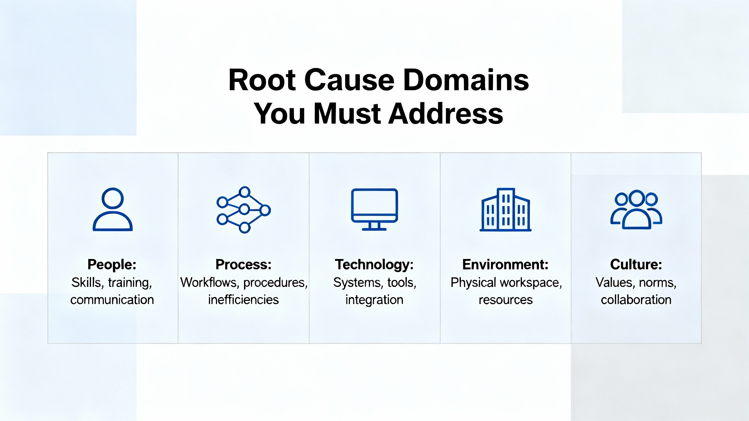
Root Cause Domains You Must Address
When you strip away the siteŌĆæspecific details, every 3500 communication problem lives in one or more of four domains: rack and power health, gateway health, network path integrity, and configuration integrity. The published documentation and case reports are remarkably consistent on this point.
Rack and Power Health
The 3500 is a critical protection system with its own power supply modules and overall rack health reporting. Official coverage from Bently Nevada and the Actech Parts 3500 guide notes that power supply failures are often traceable to power source interruptions, faulty power supply modules, or improper installation. Recommended actions include checking source connections, replacing defective supply modules, and verifying installation against official guidelines.
Although this is not a communication function, a marginal or unstable supply to the rack or gateway can produce intermittent network behavior long before it triggers a full rack shutdown. Commissioning material such as the ŌĆ£DumboŌĆØ 3500 guide emphasizes the role of a correctly sized and wired 24 VDC power supply feeding the rack, and the need to verify that DC supply before establishing communications or downloading configuration.
As a reliability advisor, I always treat rack and DC power health as the foundation. If your 24 VDC supply is derived from UPS systems or inverterŌĆæfed DC boards, transient events on those sources can manifest as flickering OK LEDs or gateway resets even if the rack never fully powers down.
Communication Gateway Health
The 3500/92 Communication Gateway sits at the boundary between the protection rack and the wider plant network. According to the Baker Hughes datasheet, it is installed in a standard rack slot, powered from the rack, and designed to aggregate static data and status from the backplane and expose it via Ethernet or serial protocols. It is explicitly not intended as the sole means of implementing trip logic, which is an important safety assurance when communications fail.
In the Mark VIe gas turbine case, the gateway itself reported ŌĆ£NOT OKŌĆØ while all monitor modules reported OK, and its communication LED behavior differed from healthy units. That aligns closely with the Actech Parts guide recommendation to treat ŌĆ£module not respondingŌĆØ conditions by confirming the presence and stability of power, swapping out malfunctioning modules, and reconfiguring module settings as needed.
Operationally, an unhealthy gateway can behave intermittently, especially under marginal power or network conditions: it may publish data sporadically or fail entirely while local rack data remains valid. The fact that configuration tools can still read rack data while the gateway to the DCS does not respond is a strong diagnostic indicator that the fault is concentrated at the gateway or its immediate network port.
Network Path Integrity
Everything between the gateway Ethernet or serial port and the DCS or PLC input card falls into this domain: patch cords, managed or unmanaged switches, VLANs, firewalls, and longer fiber or copper runs. The Ubest Automation article on common Bently Nevada 3500 issues emphasizes that communication failures are often due to physical network problems or misconfigurations, and gives a clear example where replacing a network switch and updating firmware eliminated repeated communication drops.
The control.com discussion reinforces this perspective by recommending examination of shared network paths and switches between the 3500 system and the Mark VIe HMIs, and correlating the recurrence of failures with any events on the EGD network. Even when plant staff visually inspect Ethernet cabling and initially discount simple cable faults, it is still essential to consider the broader network infrastructure.
For EGDŌĆæbased systems, the network path is part of maintaining deterministic data exchange. Interruptions, overload, or misrouting on this path can cause the HMIs to stop receiving vibration data even if the EGD server service is reported as running.
Configuration and Protocol Integrity
Configuration errors span both sides of the interface. On the 3500 side, the Rack Configuration and Utilities Guide describes how to set the 3500/92 communication parameters, select the protocol, define addresses, and map channels and statuses to communication points. On the host side, the Computer Hardware and Software Manual covers how to connect the rack to the host computer, configure Data Acquisition or DDE servers, and verify communications.
The Ubest Automation guide on 3500 communication issues highlights that incorrect protocol settings or IP addresses are common causes of data not reaching the DCS or PLC. The Actech Parts 3500 overview similarly notes that incorrect configuration settings can cause communication failures, and recommends correcting configuration parameters after inspecting cables and suspect modules.
Configuration errors can be subtle: an incorrect node address, an overlap in IP addressing, or a mismatch between the gatewayŌĆÖs channel mapping and the DCS expectation can all appear as generic ŌĆ£communication errorŌĆØ alarms.
Network Restoration Strategy: A Practical Sequence
In real plants, the temptation is to jump straight to swapping modules or blaming the network. The most dependable results, however, come from a structured approach that starts with safety, validates the 3500ŌĆÖs protective function, and then moves outward through the gateway and network. The sequence below is drawn directly from official 3500 documentation, commissioning guides, and the field cases already discussed.
Confirm Protection and Safety Before Diving Into the Network
The first responsibility is to confirm that the machine is still protected before you treat the situation as a purely communication problem. The 3500/92 datasheet and related literature are clear that the gateway is a data and status interface, not a protection device. The protection logic resides in the monitor modules and rackŌĆælevel relays.
On the rack front panel, confirm that the monitor modules that generate vibration, position, and temperature alarms are all in an OK state. The 3500/42 Proximitor/Seismic Monitor documentation defines the OK and Not OK status concepts clearly and explains that channel OK indicates valid transducer and channel health. If those modules remain OK and your trip relays and wiring have not been bypassed, the machine protection function remains intact even if the gateway is not delivering data to the DCS.
If there is any doubt about protection, address that first, following your siteŌĆÖs formal procedures, before experimenting with communication settings or replacing network hardware.
Check 3500 Rack Power and Overall Health
Once protection is confirmed, the next step is to confirm that the 24 VDC supply and rack power modules are healthy. The commissioning guide often referred to as the ŌĆ£DumboŌĆØ guide includes an explicit section on the 24 VDC power supply, with an emphasis on verifying correct DC voltage and polarity before proceeding with configuration and communication setup.
The Actech Parts technical guide notes that power supply failure causes include power source interruption, faulty power supply modules, or improper installation. Recommended actions are to check source connections, replace defective modules, and verify against official installation guidelines. A marginal supply can easily lead to intermittent gateway behavior or flickering OK LEDs, particularly where the rack power system shares infrastructure with UPS or inverterŌĆæbased DC systems.
From a power system perspective, I always ask whether any recent work has been done on DC boards, UPS systems, or inverter outputs feeding the rack. If a communication problem correlates in time with a DC power event, treat the rack power interface as a priority.
Validate That the Rack Is Collecting Good Data Locally
With rack power verified, you must distinguish between a measurement problem and a communication problem. The vibration troubleshooting guide from Inst Tools and the LinkedIn technical note on Bently Nevada proximity probes both stress the importance of verifying probe health, cable integrity, and proximitor operation using basic checks such as visual inspection, gap voltage stability, resistance measurement, and linearity tests with a micrometer.
In the Mark VIe gas turbine case, an engineering laptop running Bently Nevada Rack Configurator software was used to directly interrogate the rack. All 3500 channels read correctly and all modules reported an OK condition. This is a key step: if the rack can be read locally via its configuration port and all measurements look reasonable, then your 3500 monitoring path is likely healthy, and you can confidently focus on the communication chain to the DCS.
If local checks show Not OK statuses or invalid readings, solve that measurement problem first using the established vibration and temperature troubleshooting practices. There is no benefit in chasing network issues if the underlying monitoring is already compromised.
Inspect the 3500/92 Gateway Status and Power
Once you know the rack and measurements are healthy, focus on the gateway. Check its frontŌĆæpanel OK and communication indicators, and compare their behavior with a known good unit if you have one. In the Mark VIe example, the problematic unit showed a communication LED off and an OK LED flickering, while healthy units showed steady green OK and active communication.
The Actech Parts guideŌĆÖs general advice for a ŌĆ£module not respondingŌĆØ condition is directly applicable here: confirm that power is present and stable at the module, swap out malfunctioning modules with known good spares, and reconfigure module settings if needed. Because the 3500/92 is powered from the rack, any noise or dropouts on the rack supply may show up first as erratic gateway behavior, so this step completes the check that began with rack power.
If you have a redundant gateway or the option to temporarily slot a spare that has been configured for your rack, this is the time to do it under controlled conditions. A spare that behaves normally under the same network and rack conditions strongly suggests a hardware fault in the original module.
Trace the Network Path Between Gateway and Host
When the gateway looks healthy, move outward to the network. The 3500/92 datasheet and the 350091M EGD communication gateway document emphasize that the gateway provides a defined interface boundary between the rack and the wider plant network, and that network configuration should follow site security and design practices.
The Ubest Automation guide on common 3500 issues recommends verifying cabling and connectors and confirming protocol parameters and IP addressing in the configuration software when communication failures occur. Their case study on repeated communication drops between a 3500 and an AllenŌĆæBradley PLC concluded with a failed network switch and the need for a firmware update. Once the switch was replaced and firmware updated, communication stabilized.
In practice, this means verifying the physical connection from the gateway port to the first switch, ensuring link status is good at both ends, and reviewing any recent changes to switch configuration, VLANs, or access control that could affect the 3500ŌĆÖs traffic. For EGDŌĆæbased architectures, ensure that the EGD data consumers and the gateway are on the expected network segments and that no new filtering rules block or rateŌĆælimit EGD traffic.
From a power and reliability standpoint, also consider the power supply of the network infrastructure itself. Switches and routers that share UPS power with other loads may experience momentary brownouts or restarts during battery tests or transfer events, which can manifest as shortŌĆælived communication losses that repeat on a schedule.
Validate Configuration on Both the 3500 and the Host Side
After confirming hardware and network connectivity, you must check configuration integrity at both ends. The Rack Configuration and Utilities Guide provides guidelines for configuring the 3500/92 module, including protocol selection, IP addressing, node or Modbus ID assignment, and mapping of 3500 channels and statuses to communication registers. The guide also recommends using builtŌĆæin test utilities to verify that input and output terminals are working correctly.
On the host side, the Computer Hardware and Software Manual for the 3500 system explains how to install and configure the host connection, including Data Acquisition or DDE Server software, and how to verify communications. It also addresses network and remote communication settings that may affect the visibility of 3500 data on HMIs or historians.
The Ubest Automation communication troubleshooting article underscores that incorrect protocol settings or IP addresses are frequent root causes when the DCS or PLC does not receive 3500 data. A careful comparison between the gateway configuration and the host expectation is essential. Pay particular attention to address ranges, polling rates, and whether any data map changes have been made recently on either side.
Correlate Communication Failures With Events and Patterns
At this stage, you will often have narrowed the issue to a specific component or misconfiguration. To confirm root cause, correlate failure times with plant events. The control.com Mark VIe case notes that communication failures appeared across multiple units within less than an hour, and recommends correlating this recurrence with any scheduled tasks or events on the EGD network.
From a reliability engineering standpoint, repeating failures that line up with specific time windows often point to scheduled tasks, such as network scans, firmware updates, or even UPS battery tests and transfer operations. Repeated failures during heavy load or during other network changes may indicate bandwidth or qualityŌĆæofŌĆæservice limitations that selectively impact vibration data streams.
Documenting these correlations strengthens the case for targeted corrective actions, whether that means replacing a particular switch, revising network segmentation, or adjusting host polling and timeouts.
Escalate With the Right Documentation When Needed
If you have validated rack health, gateway status, network path, and configuration, and communication is still unstable or failed, it is time to escalate. The 3500/92 Operation and Maintenance information explicitly states that the manual is not standalone and directs users to the broader 3500 documentation set, including the Rack Installation and Maintenance Manual, the Rack Configuration and Utilities Guide, the Computer Hardware and Software Manual, and the Field Wiring Diagram Package.
When involving OEM support or a specialist integrator, arrive with the following already captured: a clear description of symptoms on both the 3500 and DCS sides, snapshots of gateway LED status and diagnostics, network topology and any recent changes, and exported 3500 configuration files. Vendors such as Ubest Automation, who position themselves as providers of genuine parts and configuration assistance for Bently Nevada systems, explicitly recommend seeking professional support for complex or persistent issues.
In many cases, formal training programs such as the threeŌĆæday Bently Nevada 3500 monitoring system course offered by MBESI or similar troubleshooting courses listed by Cordant Training can significantly improve inŌĆæhouse capability to diagnose and solve these problems before escalation is needed.
Power Supply and UPS Considerations Around 3500 Communications
From a power systems point of view, it is not enough to treat the 3500 rack and its communication gateway as isolated components. Commissioning documentation for the 3500 makes clear that a correctly rated 24 VDC supply is required, and in most modern plants that DC source is tied into UPS or inverter systems designed to keep protection and control equipment energized during disturbances.
The same DC and UPS infrastructure often feeds network switches, HMI workstations, and other communication devices. If those supplies are undersized, miswired, or subject to transient disturbances, a communication failure may actually be a symptom of a deeper power quality issue. For example, a voltage sag on a DC distribution panel can reset a network switch or cause a gateway to momentarily lose power, even if the 3500 rack appears to stay up.
The general guidance from power reliability work applies here: ensure that the 24 VDC supply specified in the 3500 commissioning guide has adequate headroom, is correctly fused, and is not overloaded by additional DC consumers added over time. Where possible, allocate critical protection and communication devices to stable, wellŌĆæmaintained UPS sources and avoid mixing them with large, noisy loads that can inject disturbances onto the DC bus.
When you see recurring communication faults that line up with battery tests, generator transfer operations, or other power events, bring your power quality monitoring data into the 3500 troubleshooting discussion. In many cases, resolving a DC or UPS issue will stabilize both communication and other plant control systems.
Brief FAQ: Key Questions About 3500 Communication Errors
Is my machine still protected when I lose 3500 communication to the DCS?
According to the 3500 system architecture and the 3500/92 datasheet, protection logic resides in the monitor modules and rackŌĆælevel trip relays, not in the communication gateway. As long as the rack, monitors, and trip paths remain OK and have not been bypassed, the machine remains protected even if the DCS temporarily loses visibility of 3500 data. That is why the first troubleshooting step is to confirm rack and protection health before working on the network.
When should I suspect the network instead of the 3500 rack?
If a laptop running 3500 configuration software can read the rack without issue, and monitor modules show OK status while the DCS still cannot see vibration data, the problem is almost certainly in the gateway, network path, or host configuration. Case studies from control.com and Ubest Automation both show that replacing a network switch or addressing network configuration resolved repeated communication drops without any changes to the 3500 rack itself.
Do I need redundant gateways or networks?
The 3500/92 datasheet and general 3500 system guidance recommend considering redundant gateways or network paths where high availability is required, with the understanding that the gateway is a data interface only. For critical assets where continuous condition monitoring is essential, redundant communication paths can prevent data loss during single component failures, even though machine protection itself is already implemented redundantly in the 3500 rack.
References and Knowledge Sources
The practical approach outlined here is anchored in several key sources. Baker Hughes documentation for the Bently Nevada 3500 system, including the 3500/92 Communication Gateway datasheet, the Rack Installation and Maintenance Manual, the Rack Configuration and Utilities Guide, the Computer Hardware and Software Manual, and the Field Wiring Diagram Package, defines the official behavior and configuration of racks and gateways. An inŌĆædepth Actech Parts technical guide on the 3500 system summarizes typical failure modes and corrective actions for power and communication issues. Ubest AutomationŌĆÖs articles on troubleshooting common 3500 issues and on 3500 module behavior provide fieldŌĆæoriented examples of communication failures resolved through network and configuration corrections. A commissioning guide sometimes referred to as the ŌĆ£DumboŌĆØ guide on Scribd adds detailed stepŌĆæbyŌĆæstep practices for establishing communication and validating rack configuration. RealŌĆæworld cases shared on control.com forums illustrate how 3500/92 EGD gateways behave during Mark VIe communication failures and highlight the importance of correlating faults with network events.
Together, these sources align closely and support a systematic, safetyŌĆæconscious approach to restoring communications without compromising the protection role that the 3500 plays in your rotating machinery portfolio.
In the end, a Bently Nevada 3500 communication error is rarely a mystery. When you start with protection, respect the power and DC supply fundamentals, and then walk methodically through the gateway, network, and configuration layers, you not only restore the data that operators depend on, you also harden the entire protection and communication chain for the next disturbance.
References
- https://www.waterboards.ca.gov/water_issues/programs/ocean/cwa316/docs/cwa316_2009sept/comments/mark_krausse_2.pdf
- https://projects.mcah.columbia.edu/amiens-arthum/sites/default/files/VR/North/?pano=data:text%5C%2Fxml,%3Ckrpano%20onstart=%22loadpano(%27%2F%5C%2F1mg.pics%2Fp%2F34720595069%27)%3B%22%3E%3C/krpano%3E
- https://studylib.net/doc/27017185/bently-nevada-3500-proximitor
- https://www.plctalk.net/forums/threads/bently-3500-92-prosoft-mvi56e-mnet-comm-woes.120249/
- https://actechparts.com/bently-nevada-3500-complete-guide/
- https://www.artisantg.com/info/GE_Bently_Nevada_3500_42_Manual_20171113133924.pdf?srsltid=AfmBOopfq75uXEcQjRgF68bpAkTI7jSjNNajsb1i3ib3Z4fkXHjJ-Ft_
- https://instrumentationtools.com/vibration-monitoring-system-step-by-step-troubleshooting-guide/
- https://www.linkedin.com/posts/arham-ashfaq_troubleshooting-bentlynevada-probes-activity-7121785098005360640-6BcQ
- https://cordanttraining.com/course/3500-monitoring-system-troubleshooting/
- https://mbesi.com/site/3500-monitor-system-training/


 Videos
 News
News Applications


Leave Your Comment