Allen-Bradley 1756 ControlLogix systems sit at the core of many industrial and commercial power installations, often coordinating UPS-fed switchgear, critical HVAC, process loads, and safety systems. When a 1756 chassis faults, the impact is immediate: lines stop, transfer switches misbehave, and power quality events ripple across the plant. In facilities where downtime is measured in thousands of dollars per minute, disciplined fault diagnosis is no longer ŌĆ£nice to haveŌĆØ; it is a reliability requirement.
As a power system specialist who spends as much time inside control panels as in switchrooms, I see the same pattern repeatedly. The ControlLogix hardware is generally solid, but small issues in power, grounding, configuration, or networks expose themselves as red LEDs and obscure fault codes. The good news is that the major repair shops, training providers, and RockwellŌĆÖs own documentation all point to a repeatable way to get your 1756 system back on its feet quickly and safely.
This article unpacks those procedures into a practical diagnostic approach, grounded in real-world guidance from Rockwell Automation literature, industrial repair houses, and long-time instructors who teach troubleshooting on ControlLogix every week.
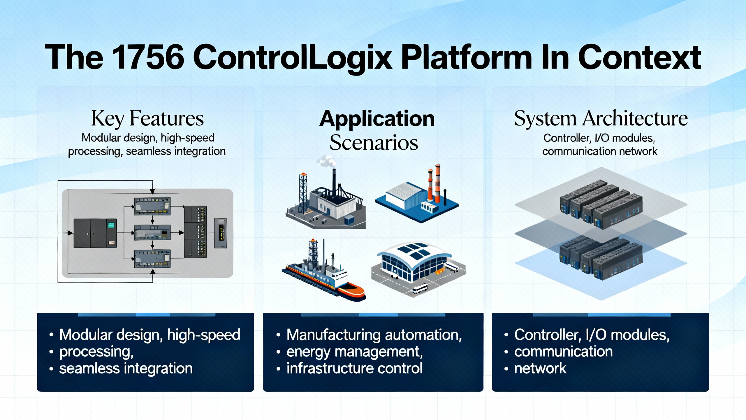
The 1756 ControlLogix Platform In Context
ControlLogix is not a ŌĆ£classic PLCŌĆØ in the older sense; it is a modular programmable automation controller (PAC). That difference matters for troubleshooting.
Traditional PLCs running RSLogix 500 are simpler, heavily ladder-centric, and provide very transparent data tables. Instructors with decades of experience, such as those at BIN95 Vocational Courses, routinely show technicians how to trace a fault through RSLogix 500 logic and find the offending sensor in four to fifteen minutes in a plant they have never seen before. Once you move into Logix 5000 and ControlLogix, the power and flexibility grow, but so does complexity: multiple programming languages, tag-based addressing, and distributed I/O and networks.
A 1756 ControlLogix system typically contains a chassis, one or more power supplies, one or more controllers, I/O modules, and communication modules sharing a common backplane. RockwellŌĆÖs ControlLogix system manual describes how these components are distributed across multiple chassis and industrial networks so that a single controller can supervise many remote racks.
From a fault-diagnosis perspective, you are dealing with at least four layers at once: control power and environment, chassis and modules, application code and memory, and networks. Faults can originate in any one of these layers, and the best diagnosticians are those who can quickly narrow down which layer is guilty.
Fault Categories You Will See
RockwellŌĆÖs Logix 5000 fault documentation and field experience from repair firms divide the symptoms into a few practical categories. You will see controller major faults, minor faults, and I/O faults inside the CPU; module-level hardware faults on power supplies, I/O, or comm modules; and network-level faults on EtherNet/IP or other networks such as ControlNet or DeviceNet.
The table below summarizes these categories and how they typically present.
| Fault category | Typical indicators | Typical impact on the system |
| Controller major fault | CPU OK LED flashing red, fault codes in Studio 5000 or RSLogix 5000 | Program scan stops; outputs may de-energize depending on configuration |
| Controller minor fault | Recorded in fault history, often no change in LEDs | Diagnostics only; program usually continues running but points to logic or config issues |
| I/O fault | I/O LEDs red or off, I/O module OK flashing red | Lost or frozen inputs/outputs, devices not responding |
| Module hardware fault | Solid or flashing red OK LED on a 1756 power supply, controller, or I/O module | Chassis segment, controller, or I/O channel stops working |
| Network/connection fault | EtherNet/IP timeout codes, network status LEDs red, communication timeouts | Loss of comms to remote I/O, drives, HMIs, or peer controllers |
| Configuration/firmware mismatch | Fault codes pointing to configuration errors, module mismatch, or version mismatch | Modules not recognized, connections not established, unexplained faults and dropouts |
In practice, multiple categories often overlap. A grounding problem on a 1756 chassis, for example, can cause power supply faults, network noise, and spurious I/O timeouts all at once. The point of a good diagnostic procedure is to separate those layers methodically rather than chasing symptoms in circles.
A Practical 1756 Fault Diagnosis Workflow
Every plant, integrator, and OEM has its own flavor of troubleshooting, but the most effective approaches all follow the same backbone taught in RockwellŌĆÖs ControlLogix maintenance courses and in hands-on classes from providers such as BIN95, Opensoft Systems, and RockwellŌĆÖs CCP153 instructor-led training. The sequence is simple: read what the hardware tells you, then confirm and deepen that picture in Studio 5000, then discriminate between power, hardware, configuration, and network causes before you reset or replace anything.
Start With LEDs and the Hardware In Front Of You
ControlLogix and 1756 modules provide a lot of information through their front-panel indicators. Training material and field guides consistently recommend starting here, long before reaching for a replacement module.
On the controller, pay attention to the RUN, OK, and I/O LEDs. A solid green RUN with a solid green OK generally indicates the controller is executing as expected. A flashing or solid red OK LED signals a major fault. The I/O LED tells you whether the controller is happy with its I/O connections; a red state indicates that something about the I/O configuration or communications is wrong.
On 1756 power supplies, a solid red LED often indicates an overload condition. Repair specialists who focus on ControlLogix hardware note that a red LED on a 1756-PB-series module is frequently the sign of an overloaded or failing supply rather than a mysterious software issue. Flickering LEDs on I/O modules can mean that the module is not communicating properly with the controller over the backplane, even when the module hardware itself is still healthy.
I/O modules add their own OK, I/O, and sometimes network status LEDs. For local and networked I/O, the combination of these LEDs tells you whether the fault is in the field device, the module, the backplane, or the network link. A red OK LED on a specific 1756 I/O module narrows the search dramatically compared to a global communication alarm in a SCADA system.
Matching LED states and flash patterns to the fault tables in the module and system manuals is not optional. Guides from Rockwell Automation and service firms emphasize this first step because it anchors your diagnosis in how the device itself sees the fault, not in how operators describe the symptom.
Go Online With Studio 5000 Or RSLogix 5000
Once you have a picture from the hardware, the next step is to go online with the controller using Studio 5000 Logix Designer (or RSLogix 5000 on older systems). This is where you confirm the fault type and collect the details that the LEDs alone cannot show.
ControlLogix troubleshooting articles and training guides consistently highlight a few key screens. The controllerŌĆÖs Fault tab in Controller Properties shows major and minor faults with their type and code. This is also where you will see watchdog timeouts, array index errors, divide-by-zero operations, and other logic-related problems that stop the processor.
For 1756 systems, the Module Info or Module Properties screens let you drill into individual modules in the I/O tree. If an I/O module is flagged as faulted, you can see whether the problem is a lost connection, a configuration mismatch, or an internal error.
Real-world troubleshooting guides from Global Electronic Services and Industrial Automation Co. stress the importance of capturing the exact fault code and any extended data, together with the controllerŌĆÖs fault history. This history reveals whether you are dealing with a one-off event or a recurring pattern linked to a particular operating condition, time of day, or upstream power event.
While online, monitoring the relevant tags is equally important. If an input device is suspected, watching the corresponding input tag while manually actuating the device tells you whether the signal dies at the field level, at the I/O module, or somewhere in the logic. Similarly, monitoring outputs reveals whether the controller is trying to energize a device that never moves, which points more toward hardware or power issues in the field.
Separate Power And Environmental Issues From Logic Problems
Experienced Rockwell service partners and training providers all emphasize the same point: you should clear power and environmental suspects before rewriting code. Articles from HESCOŌĆÖs engineering blog and maintenance specialists such as Hale Engineering, as well as 1756-focused hardware troubleshooting guides, highlight power supply and environmental degradation as some of the most common root causes behind ŌĆ£mysteryŌĆØ ControlLogix behavior.
For 1756 systems, this means verifying that the chassis power supply is correctly sized and not operating beyond its current rating when all modules and loads are active. In one industrial case, technicians traced intermittent ControlLogix shutdowns to a power supply that was marginal under normal load and consistently dropped out during startup surges. Upgrading to a higher-capacity supply stabilized the system without any changes to logic.
Power problems do not end at the module. Seal-tight or cable trays that also carry large motor leads or drives can induce noise into low-voltage control wiring. Loose or corroded grounds on the 1756 chassis can cause apparent module failures and intermittent network faults that disappear once the ground is re-terminated correctly. One 1756 audit cited in a module troubleshooting guide found that roughly forty percent of modules flagged as ŌĆ£failedŌĆØ were actually misconfigured or affected by grounding or firmware issues rather than true hardware defects.
Heat is another silent killer. Hale EngineeringŌĆÖs PLC health check guidance recommends regular inspection of cabinet temperature, airflow, and signs of heat stress on I/O modules, power supplies, and communication cards. A control panel that routinely runs near the top of a typical ControlLogix temperature range, roughly 140┬░F, will age components much faster than a cooler, well-ventilated cabinet, particularly when it also houses UPS equipment, power supplies, or inverters that dissipate significant heat.
Prove Your Networks And I/O Paths
Modern 1756 systems rarely operate as isolated islands. EtherNet/IP is usually the backbone connecting controllers, remote I/O, smart MCCs, UPS-monitoring gateways, and HMIs. Network-related faults therefore appear frequently in ControlLogix fault logs.
Repair and diagnostics sources describe several EtherNet/IP error codes that recur in the field. An I/O timeout fault indicates that the controller has stopped hearing from a remote module within the expected time. EtherNet/IP timeout codes point towards network congestion or failing switches. Duplicate IP address codes almost always result from misconfigured devices, such as a spare I/O rack or HMI panel that was cloned without updating its IP settings.
Practical EtherNet/IP guides emphasize verifying that the engineering laptop and the PLC network are on the same subnet, that Auto Browse or continuous discovery is enabled in the communication tools, and that the correct network adapter and driver are selected. When the software cannot see devices that are obviously powered and connected, the cause is often a wrong IP range or a mis-selected network interface rather than a bad PLC.
For networked I/O, the most effective troubleshooting sequence is remarkably consistent across case studies. First, inspect the physical cabling for damage, loose terminations, or vibration-related wear. Second, use Studio 5000 to check the module status and I/O connection health. Third, apply network diagnostic tools to look for packet loss, excessive traffic, or port errors on switches. Finally, resolve any IP conflicts and ensure that I/O update rates and Requested Packet Intervals are realistic for the network capacity.
Locally in the control cabinet, I/O faults often turn out to be caused by loose, dislodged, or damaged field wiring. Several ControlLogix I/O troubleshooting examples show technicians resolving serious production issues simply by reseating a plug that was disturbed during maintenance or replacing a damaged sensor cable. The common thread is that physical checks come early in the sequence, not at the end.
Use Fault Codes And Fault Routines Instead Of Guesswork
Once you have confirmed that power, environment, and networks are sound, fault codes and fault routines become your next line of defense.
RockwellŌĆÖs manual on major, minor, and I/O faults, together with practical fault-handling discussions from experienced users, describes how Logix 5000 controllers respond to faults. A major fault typically stops the controller and puts the OK LED into a flashing red state. Minor faults and I/O faults can be logged without necessarily stopping execution.
Typical recoverable program faults in ControlLogix include divide-by-zero operations and watchdog timeouts, where the logic takes longer to execute than the configured tolerance. Memory-related faults such as nonrecoverable memory errors, insufficient memory, or program corruption are more serious and may require cleaning unused routines, optimizing logic, reloading a known-good backup, or even reflashing firmware or replacing a processor, depending on the diagnosis.
Logix 5000 controllers let you define program-level fault routines and a controller fault handler. Forum discussions and Rockwell documentation are clear on how these should be used. A good fault routine sets a flag to indicate that a fault occurred, captures detailed fault information into a structured tag using a Get System Value instruction, and then, if and only if it is safe, clears the fault so the system can continue or perform an orderly shutdown. The controller fault handler acts as the last resort, especially for I/O-related faults that program-level handlers do not catch.
The consistent recommendation is to resist the temptation to write routines that blindly clear every fault. Clearing all faults without discrimination may let a system restart quickly in the short term, but it also guarantees that you will miss the root cause and may restart into an unsafe or degraded state. Instead, use fault routines to log, analyze, and selectively clear specific, well-understood faults, leaving anything ambiguous to drive the system into a defined safe mode.
Know When To Reset, When To Replace, And When To Escalate
Guides from Industrial Automation Co. and other Rockwell specialists are explicit that a controller reset is a last resort. Before resetting a 1756 controller or chassis, confirm that you have a current, verified backup and that you have exhausted power, configuration, network, and logic diagnostics. When a reset is truly necessary, follow the published procedure, reload the validated application, and then monitor the system under controlled conditions to confirm stability.
Hardware replacement follows a similar rule. Uptime-focused hardware providers who audit 1756 modules report that around forty percent of modules returned as ŌĆ£failedŌĆØ turned out to be misconfigured or suffering from power, grounding, or firmware mismatch issues rather than true hardware defects. Their standard field process starts with LED interpretation, fault code review, grounding checks, and firmware comparison. Only after software diagnostics do they swap in a pre-tested spare with the same firmware revision. This approach protects both uptime and budget, while avoiding the introduction of new variables into an already stressed system.
Escalation to external experts makes sense when faults span multiple systems or protocols, when you suspect corrupted programs or serious memory allocation issues, or when there is no reliable backup of the running application. At that point, engaging Rockwell TechConnect support or a specialist repair house is often more cost-effective than trial-and-error in a live plant, especially in facilities where power continuity and safety obligations are strict.
Common 1756 Fault Scenarios And How To Approach Them
Within that workflow, certain fault scenarios show up again and again in power-critical ControlLogix installations.
Power Supply And Chassis Issues
Symptoms of power-related faults include intermittent controller restarts, multiple modules dropping out at once, I/O that occasionally freezes and then recovers, and red LEDs on a 1756 power supply. Visual inspection frequently reveals crowded cabinets, fans that no longer move air effectively, or evidence of heat stress on plastic bodies and connectors.
Hale EngineeringŌĆÖs best-practice checklists recommend verifying power and environmental conditions as part of every PLC health check. For 1756 systems, that means confirming the incoming voltage is within specification, ensuring your power supply capacity exceeds the sum of chassis loads with margin, and inspecting grounding and bonding between the chassis, control cabinet, and plant grounding system. In many modern installations, the same UPS or DC power bus supports ControlLogix racks and sensitive protection or monitoring equipment, which means any overload, low battery condition, or failing UPS component can cascade into PLC faults.
In such cases, it is not enough to replace the PLC power supply. The upstream UPS capacity, load distribution, and thermal environment must be reviewed so that the next high-load event does not produce the same fault again.
Controller Major Faults And Memory Errors
When the controller itself faults, technicians often see a flashing red OK LED, the controller in Program or Fault mode, and fault entries in the controller properties. Common major faults include divide-by-zero errors, out-of-range array indexing, watchdog timeouts indicating that a task overran its allowed execution time, and access to invalid memory regions.
Global Electronic Services and other repair providers describe specific fault codes that help narrow down the cause. For example, a recoverable program execution fault code may indicate a divide-by-zero error; a watchdog timeout code signals that the logic needs optimization or that a periodic task is configured with an unrealistically short period. More serious codes, such as nonrecoverable memory errors or program corruption, point toward deeper issues: controller memory failures, firmware problems, or corrupted downloads.
The recommended process in these cases is disciplined. First, record the exact fault code, extended code, time, and operating context. Second, analyze the logic around the faulted instruction, correcting any obvious programming errors such as unchecked division, invalid indirect addressing, or overly heavy tasks. Third, review controller memory usage, trimming unused code and tags or upgrading hardware if the project has grown beyond the original platformŌĆÖs capability. Finally, if corruption is suspected, reload a known-good, validated backup and, where needed, reflash the controller firmware following RockwellŌĆÖs procedures.
In all steps, documentation matters. Repair organizations and RockwellŌĆÖs own training emphasize detailed fault logs shared between shifts so that patterns are recognized and not treated as isolated events.
I/O Module And Field Device Problems
I/O problems in ControlLogix systems manifest in practical ways: motors that refuse to start despite commands, limit switches that always appear inactive, analog inputs stuck at zero or at full scale, or safety devices that trip unexpectedly. The sources can be faulty field devices, damaged wiring, failing I/O modules, or misconfiguration in the I/O tree.
I/O-focused troubleshooting guides for ControlLogix recommend starting with the module LEDs and Studio 5000 diagnostics, then quickly moving to the physical layer. Ensuring that the module is firmly seated in the chassis, that terminal blocks or removable connectors are fully latched, and that field wiring is secure and undamaged often clears apparently serious faults in minutes. In high-vibration or high-traffic areas, dislodged connectors are common, especially after other maintenance work in the same cabinet.
Configuration errors are another frequent culprit. If the wrong module type is configured, if the slot addressing does not match the physical layout, or if I/O update rates are set unreasonably fast or slow, the controller may repeatedly flag faults or show inconsistent data. Updating firmware to match controller revisions and checking compatibility tables is also part of the standard resolution path, since firmware mismatches can look like hardware faults.
The consistent message from case studies is that I/O troubleshooting pays off when it is systematic and evidence-based, not when technicians immediately swap modules or devices without confirming what the controller actually sees.
Network And Communication Faults
In distributed ControlLogix architectures, communication faults can be as disruptive as power loss. Common symptoms are remote I/O racks dropping offline, HMIs losing tags, drives that go into communication loss fault, or SCADA systems that intermittently display stale values.
Network troubleshooting workflows recommended by Rockwell-focused training and service organizations share several elements. First, confirm physical cabling and switch status, including link lights, port errors, and any obvious signs of damage or moisture. Second, verify that there are no duplicate IP addresses, incorrect subnet masks, or mismatches between device configurations and the network design. Third, ensure that engineering tools are using the correct network adapter and that discovery or browsing is active so that devices appear as expected.
EtherNet/IP-specific fault codes provide extra precision. I/O timeout codes tell you that specific connections are not being serviced within their deadlines, pointing toward overloaded networks, bad switches, or devices that are powered but not responding. EtherNet/IP timeout codes relating to congestion reveal that network bandwidth or switch performance has been exceeded, often during peak production or during mass firmware updates. Duplicate IP address codes call for an immediate survey of the network to find and correct misconfigured devices before they cause broader instability.
In power-critical environments, it is especially important to remember that the same network may carry both protection device communications and ControlLogix I/O traffic. Improving the network design by segmenting traffic, prioritizing critical packets, and ensuring adequate switch performance does as much for PLC reliability as changing logic ever will.
Intermittent And ŌĆ£PhantomŌĆØ Faults
Some of the most difficult 1756 problems are those that clear themselves before anyone arrives. Intermittent faults are particularly common in plants where environmental, power, or network stress peaks at certain times: startup, large motor inrushes, or switching events on utility feeders or UPS systems.
Rockwell-oriented troubleshooting guides and industrial repair blogs recommend a few strategies here. One is to rely heavily on controller fault histories, trend logs, and diagnostic event logs from Studio 5000 or the surrounding FactoryTalk ecosystem. Another is to bring in additional diagnostic tools such as thermal imaging for panels, vibration analysis for enclosures, and network analyzers that can capture transients and bursts that are not visible during a quick visual inspection.
In many cases, the resolution is ultimately simple: a re-terminated ground, a derated UPS or power supply, a better-ventilated cabinet, or a corrected network configuration. What distinguishes successful plants is not luck but the discipline to document every intermittent event and address it systematically before it becomes a hard failure.
Turning Diagnostics Into A Reliability Strategy
Good fault diagnosis is not just a way to put out fires more quickly. It is a feedback loop that should drive how you maintain, upgrade, and protect your ControlLogix infrastructure and the power systems that support it.
Maintenance And Health Checks For ControlLogix Racks
Maintenance specialists who conduct ControlLogix health checks across industries recommend structured, periodic reviews. For most sites, a six to twelve month interval for detailed PLC maintenance is appropriate, with quarterly reviews of firmware versions, memory usage, and network health. These reviews include visual inspections of wiring and terminations, checks for corrosion or loose connections, verification of cabinet temperature and airflow, and inspection of module and chassis status indicators.
Warning signs that a deeper health check is urgently needed include slower scan cycles, unresponsive or delayed I/O, intermittent communication errors, unexpected controller reboots, hot control panels, or a general feeling among operators that ŌĆ£the system is getting flaky.ŌĆØ Addressing those signals early reduces unplanned downtime and protects both the PLC and the power equipment it controls.
Backup, Firmware, And Configuration Management
Reliable 1756 fault diagnosis depends on strong configuration control. HESCOŌĆÖs lifecycle and reliability guidance, along with recommendations from Hale and others, sets a clear baseline. Controller and I/O firmware should be reviewed and updated on a regular, planned basis, ideally after testing in a non-critical environment. ControlFlash and its successors provide the tools; the key is disciplined scheduling.
Backups are equally non-negotiable. At minimum, 1756 projects should be backed up after every logic or configuration change and on a regular schedule, such as quarterly. Those backups should be stored securely and tested through restore exercises so that technicians are confident the files are usable in an emergency. Centralized asset management tools can help automate backups, version control, and restore procedures across a fleet of controllers.
Configuration management also extends to spare hardware. The most effective plants keep pre-configured, clearly labeled spare 1756 modules on hand, with firmware versions matched to the running systems. This practice dramatically reduces swap time and avoids introducing version mismatches in the middle of a fault response.
Training, Documentation, And Culture
Even the best diagnostic tools are ineffective without people who know how to use them. RockwellŌĆÖs own instructor-led troubleshooting courses, independent ControlLogix training programs, and hands-on seminars from long-time instructors all exist for a reason: they shorten the learning curve.
From a reliability advisorŌĆÖs perspective, the goals for your team are straightforward. Every technician who might be called to a 1756 cabinet should know how to go online with Studio 5000 or RSLogix 5000, interpret basic fault codes and LED patterns, monitor tags, and navigate the I/O configuration tree. They should also be familiar with plant-specific procedures for backups, firmware changes, and escalation.
Equally important is documentation. Tag naming should be consistent and meaningful so that technicians can relate code to real-world devices quickly. All changes to logic, configuration, and firmware should be documented with dates, reasons, and approvals. This documentation, combined with detailed fault records, turns each incident into a learning opportunity instead of an isolated crisis.
Integrating PLC Diagnostics With Power Quality And UPS Strategy
Because ControlLogix often orchestrates switchgear, UPS systems, and other critical power elements, its fault history is also a rich power-quality log. Many of the memory, communication, and I/O faults described in Rockwell and repair-house articles are triggered or exacerbated by upstream power anomalies: undervoltage events, repeated dips during large motor starts, failing UPS batteries, or overloaded control power transformers.
Aligning PLC diagnostics with power-system monitoring is therefore a high-value practice. When a 1756 controller logs repeated watchdog or communication faults at the same times that power quality meters see voltage sags, your remediation plan should include both improved logic resilience and improved power conditioning. That might mean rebalancing loads, increasing transformer capacity, adjusting UPS settings, or separating noisy loads from sensitive control power circuits.
Ultimately, a ControlLogix rack that never faults but sits behind an overtaxed UPS or poorly grounded distribution system is not truly reliable. The inverse is also true: a clean, redundant power system cannot compensate for undisciplined configuration management or untrained technicians. Reliability emerges when both power and control are managed as one integrated system.
Brief FAQ
What is the practical difference between a major and minor fault in a 1756 ControlLogix controller?
A major fault stops the controllerŌĆÖs scan, typically setting the OK LED to a flashing red state and forcing the processor into a faulted mode until the condition is corrected and the fault is cleared. Examples include divide-by-zero operations, watchdog timeouts, or serious memory errors. Minor faults are recorded in the controllerŌĆÖs fault history but usually do not stop execution; they act as diagnostics that should be investigated but do not immediately halt production. I/O faults are handled separately and indicate problems with I/O modules or communications.
When is it safe to automatically clear a major fault?
RockwellŌĆÖs fault-handling guidance and practitioners with deep ControlLogix experience are aligned on this: it is only safe to automatically clear a major fault when you fully understand the fault type, its cause, and the risk of reoccurrence. Typical examples include known, recoverable programming scenarios such as a periodically out-of-range recipe index that can be handled in a controlled way. Fault routines should set flags and log information first, then selectively clear only those major faults that your risk assessment and process design deem safe to clear. Generic ŌĆ£clear everything and keep runningŌĆØ routines are strongly discouraged.
How often should I back up my ControlLogix project?
Reliability-focused articles and Rockwell service recommendations converge on a simple rule: always back up after any logic or configuration change, and also on a regular schedule such as quarterly. For critical power and process systems, many organizations choose even tighter intervals. Whatever interval you choose, combine it with tested restore procedures so that backups are not just files on a server but proven recovery tools.
Can unstable power really cause all these different fault codes?
Yes. Multiple training and troubleshooting sources highlight incorrect or unstable voltage, overloaded or aging power supplies, and excessive heat as primary contributors to a wide variety of ControlLogix faults. Unstable power can manifest as controller major faults, I/O timeouts, communication dropouts, and even apparent hardware failures that disappear once power, grounding, and thermal issues are resolved. In power-critical plants, reviewing the health and design of control power, UPS systems, and grounding is therefore a key part of any 1756 fault investigation.
In the end, effective Allen-Bradley 1756 fault diagnosis comes down to disciplined thinking applied with the right tools. Read what the hardware tells you, let Studio 5000 and the fault codes fill in the details, separate power and physical causes from logic and configuration issues, and treat each incident as input to a stronger maintenance, backup, and power-quality strategy. When you do that, your ControlLogix racks become not just devices to keep alive, but reliable, well-instrumented partners in the stability of your entire power system.
References
- https://www.academia.edu/37601778/Logix_5000_Controllers_Major_Minor_and_I_O_Faults
- https://www.slac.stanford.edu/grp/lcls/controls/global/hw/users_guides/plc/1756-um001_-en-p.pdf
- https://www.plctalk.net/forums/threads/controllogix-fault-routines.115986/
- https://blog.hesconet.com/rockwell-automation-plc-troubleshooting-common-problems-and-solutions
- https://hale-eng.co.uk/top-5-allen-bradley-plc-maintenance-best-practices-and-why-a-health-check-is-essential/
- https://www.electricneutron.com/troubleshooting-guide-for-allen-bradley-plcs/
- https://gesrepair.com/how-to-diagnose-fault-codes-on-controllogix-and-compactlogix-systems/
- https://itvtrainingcenter.com/Content/ControlLogix%20Online%20Training%20Program%20(online).pdf
- https://www.realpars.com/blog/allen-bradley-plc-troubleshooting
- https://bin95.com/articles/automation/rslogix-5000-troubleshooting.htm


 Videos
 News
News Applications


Leave Your Comment