As a power system specialist focused on high-availability plants, I see the same reliability pattern repeat: production or data center power is healthy right up to the moment it is not, and the only early-warning hints live in the Distributed Control System. Alarms raised by ABB 800xA and the connected power assetsŌĆöUPS systems, inverters, VFDs, DC drives, and switchgearŌĆötell a story in codes and context. Decoding that story quickly and correctly is the difference between a controlled intervention and an unplanned outage. This reference distills practical guidance from field experience and reputable sources to help you triage ABB DCS alarms with confidence, understand how device-level faults surface at the DCS layer, and avoid the pitfalls that prolong downtime.
Why DCS Alarms Matter to Power Reliability
A modern DCS is the backbone for situational awareness. It aggregates conditions from feeders, transfer switches, UPS and battery plants, generator controls, and the many motor systems that keep cooling water, chilled water, and air moving. When a breaker trips or a drive complains about overcurrent, the DCS is where operators first look. The challenge is that a DCS alarm is often a summary of an event that actually originated inside a connected device. A succinct message like communication fault, DC link high, or motor stall can mean different root causes depending on the model, parameter set, and operating phase.
The reliability angle is straightforward. Mean time to resolution falls when teams read alarms in context, not as isolated codes. You want the deviceŌĆÖs code, the operating state that preceded it, the environmental conditions that might have pushed it over the edge, and a pattern of prior similar events. Good DCS practice brings that context to the console. When it does not, engineers spend time in guesswork, cable swaps, and unnecessary controller ŌĆ£upgradesŌĆØ that add risk without fixing the cause.
Reading ABB Alarms the Right Way: Context First, Code Second
What an ŌĆ£error codeŌĆØ actually represents
On ABB platforms, alarms are generated at multiple layers. The DCS raises system alarms such as a controller communication failure, a function block invalid state, or a channel out-of-range. Connected devices raise their own faults like overcurrent, DC bus high or low, motor overload or stall, phase loss, or memory-card errors. The DCS may pass through the device code, translate it into a tag-specific message, or compress it into a more general condition. Two devices can share a code label and mean different things, and two models from the same family can assign different meanings to the same numeric value. This is why model-specific references and the assetŌĆÖs parameter backup are essential companions to any DCS alarm list.
Operator console, event history, and incident reports
When diagnostics are context-rich, troubleshooting becomes faster and more repeatable. ABBŌĆÖs own guidance for alarm-centric operations emphasizes decision support that blends historical trends, forecasts, workflow, and intelligent alarms so operators can move from symptom to cause without leaving the console. Alarm views grouped by function or location make it easier to see impact and probable root cause instead of chasing a flood of uncorrelated messages. Response navigation that jumps straight to trend plots, drawings, or manuals removes navigational friction. With incident reporting capable of holding thousands of records per incident, teams can compare current behavior to prior events and close the loop on maintenance actions. This style of alarm management is not a luxury; it is a prerequisite for reliable power control where minutes matter.
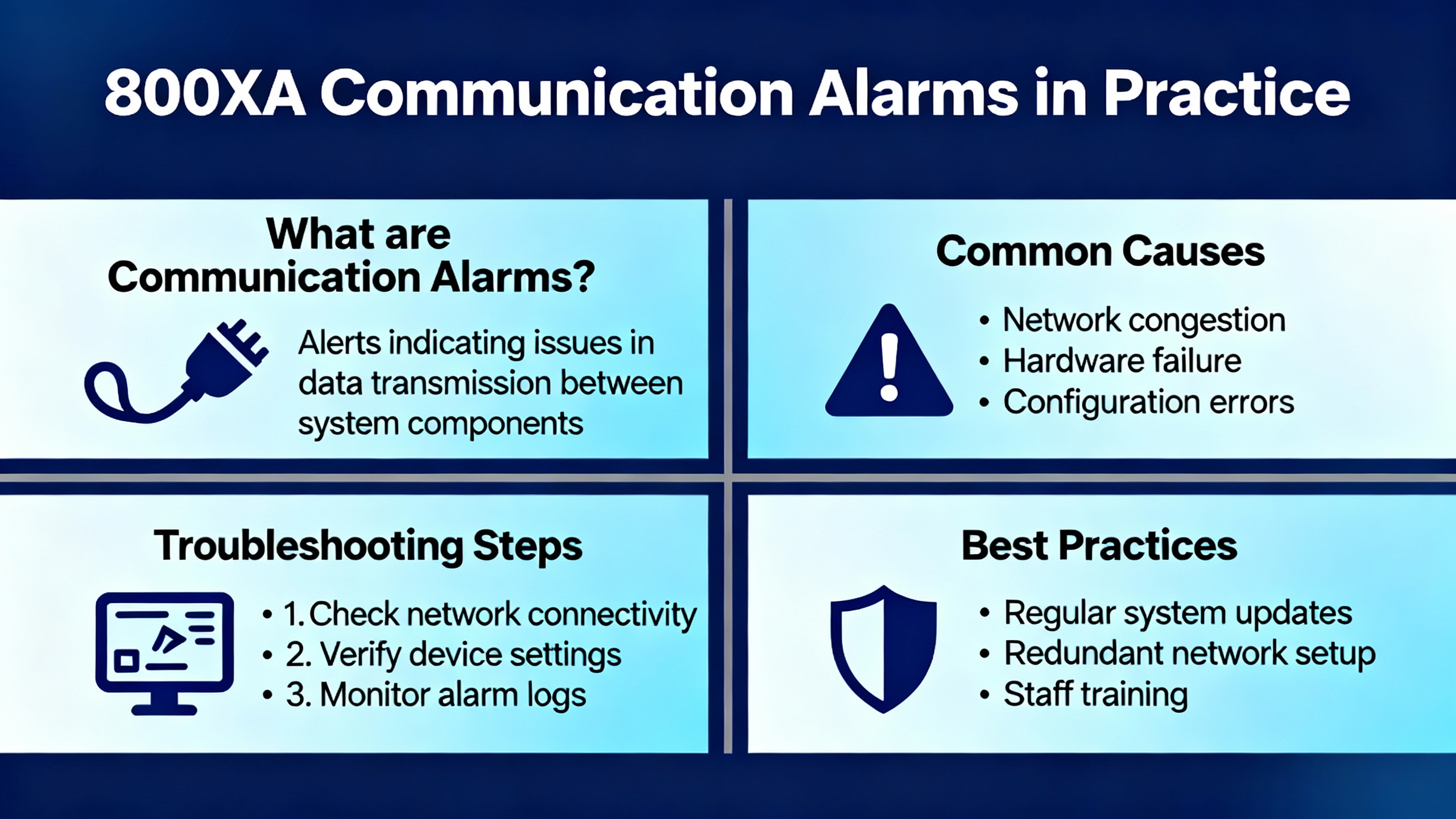
800xA Communication Alarms in Practice
Communication problems are among the most misdiagnosed issues in mixed-vendor plants because they masquerade as device faults and vice versa. A common field scenario discussed by experienced practitioners involves the 800xA CI853 module acting as a Modbus master on a serial link. If the receive indicator flashes while the transmit indicator does not, it signals abnormal link behavior; the master should not be passively receiving if it is not actively polling. When the receive light on a serial converter flashes but the device faceplate shows no valid data, it usually means the controller is attempting communications and the slave is not responding correctly.
In this situation, ŌĆ£no sign of communicationŌĆØ on a function block diagram is too vague to act on. A disciplined check goes further. Confirm whether the block is enabled, whether the connection status reports valid or a specific error, and whether any error code is visible in the objectŌĆÖs online help. Verify the correct pre-made programming cable is used when connecting locally and avoid assuming a home-made replacement is equivalent. With ABB interfaces, the recommended TK-212 or TK-212A programming cable is not a general-purpose RS232 cable; handshaking lines can be required for certain operations and a simple swap to a generic or miswired cable may prevent controller access, log retrieval, or firmware tasks even if serial signals appear electrically active.
It is acceptable to use a programming cable as a temporary diagnostic tool by connecting a workstation terminal directly to the communication module to confirm that frames are being transmitted. It is not a guarantee that the broader RS232/485 network will behave, especially when CTS and RTS lines differ between devices. In practice the remedy is to test with known-good pre-made cables, confirm the link layer parameters such as addresses and baud rate, and reseat connectors that may have oxidized. Only after you have ruled out parameter and physical-layer issues does it make sense to consider controller upgrades, and even then you should be clear about why you are upgrading rather than using version changes as a troubleshooting crutch.
Device-Level Fault Codes You Will See in the DCS
A DCS often surfaces device faults originating in drives and inverters. These are not ŌĆ£DCS errorsŌĆØ in the strict sense, but they show up as DCS alarms and must be understood at the device level to resolve them. The following tables summarize examples from reputable sources to anchor your triage.
ABB VFD fault code examples and first checks
Codes vary by product line. The same numeric code can map to different meanings across ABB drive families, which is why model-specific manuals remain essential.
| Code example | Typical meaning | First checks | Source context |
| F0001 | Internal hardware or overcurrent depending on model | Inspect output wiring for shorts, look for sudden load spikes, and consider lengthening acceleration time if applicable | Click2Electro lists F0001 as internal hardware; Delta Automation describes F0001 as overcurrent on certain models |
| F0002 | Overcurrent on some models; overvoltage on others | If overcurrent, confirm current limits and load profile; if overvoltage, verify incoming power and confirm braking resistor sizing and deceleration ramp | Click2Electro and Delta Automation each document F0002 with different meanings by model |
| F0003 | Motor overload or undervoltage depending on drive family | For overload, check thermal limits and motor sizing; for undervoltage, confirm three-phase supply and tighten connections | Click2Electro and Delta Automation list distinct definitions by model |
| F0004 | DC bus high | Review deceleration settings and braking hardware to handle regenerative energy | Click2Electro |
| F0005 | DC bus low | Check supply quality and upstream wiring including fuses | Click2Electro |
| F0006 | Motor phase loss | Inspect motor leads, terminals, and upstream protection for a missing phase or imbalance | Click2Electro |
| F0007 | Drive overtemperature | Confirm ambient conditions, fan operation, and heatsink cleanliness; restore airflow | Click2Electro |
| F0008 | Motor stall | Clear mechanical jams and review torque and acceleration settings | Click2Electro |
| F0009 | Communication fault | Verify cabling, terminations, addressing, baud rate, and reseat connectors | Click2Electro |
| F0010 | Configuration fault | Confirm parameters and model compatibility; restore a known-good parameter set where possible | Click2Electro |
| F0016 | Internal power stage fault | Power-cycle and, if persistent, plan service or replacement | Click2Electro notes internal power stage fault; Delta Automation describes internal faults requiring service on certain models |
These examples illustrate the central point. Do not assume a code is universal across ABB drives. Use the modelŌĆÖs manual and any saved parameter pack to confirm definitions before taking action.
ABB DCS 500 fault codes and typical actions
DC drives appear in DCS as critical power components for industrial processes. The DCS 500 family uses E-codes that announce hardware, sensor, and communication conditions. Typical meanings and actions are summarized here.
| Code | Meaning | Typical action |
| E001 | Overvoltage | Verify supply, review braking and deceleration settings |
| E002 | Undervoltage | Confirm supply stability and the presence of all phases |
| E003 | Motor overload | Inspect load, thermal limits, and motor sizing |
| E004 | Open circuit | Inspect power and feedback wiring |
| E005 | Power section overtemperature | Improve cooling and verify fan operation |
| E006 | Control overtemperature | Check control cabinet ventilation |
| E007 | Feedback sensor fault | Verify encoder or sensor cabling and parameters |
| E008 | Communication fault | Check bus wiring and device addressing |
| E009 | Software fault | Update firmware if recommended or contact support |
These diagnostics are intended to speed root cause identification by pairing a concise code with a short list of likely areas to investigate. They are effective only when paired with sound electrical checks, including insulation testing where ground faults are suspected.
ABB DCS800 memory card and user alarms you may see on the DCS
DCS800 drives provide detailed application and system alarms beyond power-stage conditions, including memory-card related issues and user-defined events that application logic can raise.
| Alarm | Meaning | What to do |
| A142 MemCardMiss | Application is configured but the memory card is missing | De-energize electronics, insert the correct ABB memory card into the controller board connector, re-energize; if you do not use a card, disable application save appropriately |
| A143 MemCardFail | Memory card failure, checksum error, or wrong card detected | Replace with a correct ABB card, verify application save setting, then power-cycle to clear |
| A301ŌĆōA305 | Adaptive program alarms 1ŌĆō5 | Investigate adaptive logic conditions raising the alarm and correct cause |
| A310ŌĆōA320 | User alarms 1ŌĆō10 | Review application program logic and device state to identify the trigger |
After any card change or hardware substitution, a power cycle is often required so the controller can perform a fresh read and clear related alarms cleanly.
ABB DCS400 early fault identifiers and reset behavior
For teams supporting legacy DC drives integrated into a DCS, the reset method matters because a drive made safe may not re-energize as expected. On typical DCS400 platforms, select early F-codes require a full electronics power cycle rather than a simple reset, while others can clear after the cause is corrected and a reset is issued either from the panel, a digital input, or a control-word bit on the fieldbus.
| Fault | What it indicates | Reset note |
| F2 Hardware fault or detected short in the power stage | Inspect Flash memory status and thyristor diagnostics | Some early F-codes require OFF/ON of electronics to clear |
| F3 Software fault | Record diagnosis and software version, then contact service | Power-cycle may be necessary after logging details |
| F4 Parameter flash read fault | Flash checksum failure, parameters reverted to defaults | Reload saved parameters after clearing the root cause |
| F5 Compatibility fault | Typecode or software change incompatible with stored parameters | Review diagnosis for the last affected parameter and reconfigure |
| F6 Typecode read fault | Nominal data checksum error | Reset typecode after resolving the underlying issue |
The operational takeaway is simple. Always capture diagnostic parameters and version information before cycling power or issuing a reset so post-incident analysis remains possible.
ABB DCS800 F501ŌĆōF509, as seen in user-shared lists
User-shared lists sometimes appear in operator libraries or DCS documentation sets and can be useful for first lookups. The following selection is representative and should be validated against the official manual for the exact model.
| Fault | Meaning | Validation note |
| F501 | Auxiliary undervoltage limit | Confirm supply at the specified terminal and board per model |
| F502 | Armature overcurrent | Check armature current path and load |
| F503 | Armature overvoltage | Review armature voltage feedback and limits |
| F504 | Converter overtemperature | Verify internal temperature and cooling |
| F505 | Residual current detection | Investigate ground faults |
| F506 | Motor 1 overtemperature | Check motor temperature sensor and load |
| F507 | Motor 1 overload | Review thermal model and duty |
| F508 | Option board not found or faulty | Reseat or replace the affected option board and verify bus integrity |
| F509 | Motor 2 overtemperature | Check second motor temperature channel if used |
Treat community-sourced fault tables as starting points and confirm against the official manual before changing protection settings or control logic.
A Structured Triage Workflow that Protects Uptime
Start with the DCS alarm banner, but immediately widen your view to the event history and any incident report for that asset. Look back far enough to see whether the same code appears during ramp-up, steady-state, or ramp-down. Overcurrent during acceleration requires different action than overcurrent at constant speed. If your environment supports predefined alarm navigation, jump from the alarm to the trend display for the relevant currents, voltages, and temperatures, then to the installation drawing to verify the signal chain you are about to touch.
For communication alarms, begin at the function block. Confirm that the block is enabled, the connection status message is unambiguous, and any error code reference is available. Validate the serial or fieldbus configuration against the deviceŌĆÖs settings including addresses, baud rate, parity, and handshaking. If the CI853 or equivalent is the master and its receive indicator is active without transmit activity, suspect unexpected noise or a wiring fault rather than a responsive slave. Use the correct ABB programming cable when connecting locally and avoid introducing an unknown cable variant during troubleshooting. If you must test the physical layer, a direct terminal session can prove that the master is transmitting, but it does not validate RS232 to RS485 conversion or handshaking across the entire chain.
For power-stage faults, trust the physics first. Overvoltage during deceleration often traces back to regenerative energy with insufficient braking capacity or an aggressive deceleration ramp; adjust the ramp and confirm the braking resistor and chopper are present and correctly sized. Undervoltage that appears at motor start frequently comes from a sag in the supply or a missing phase; tighten terminations, confirm upstream protection devices, and measure under load. Thermal alarms tie to airflow and ambient more often than to semiconductor failure; clear ducts, verify fans, and keep filters clean. Nuisance motor overloads usually signal a duty cycle assumption that no longer holds; review the load profile, thermal model, and motor sizing against reality.
Once the device-level cause is understood, use the DCS to close the loop. Annotate the incident, link it to a work order if your system supports it, and document the parameter changes made. Re-run the sequence that caused the trip while watching the relevant trend pages and keep the incident report open so that your observations become part of the permanent record.
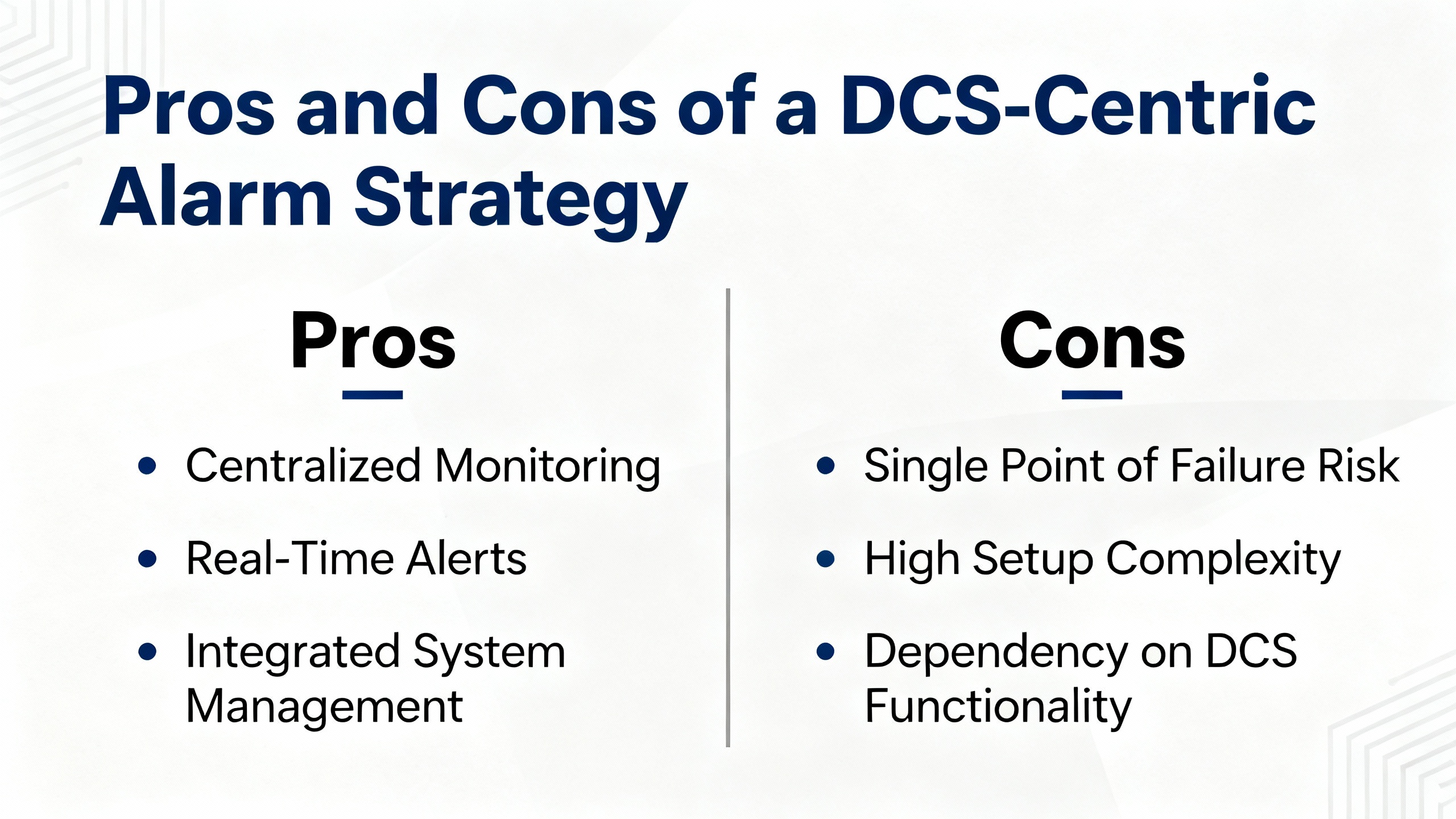
Pros and Cons of a DCS-Centric Alarm Strategy
Centralizing alarms in the DCS brings a single source of truth to operators and reduces cognitive load, especially during off-hours callouts. The obvious advantages are unified visibility, consistent workflows, and the ability to correlate across assets and time. Features like grouped alarm views, response navigation to drawings and manuals, and rich incident reports make it easier to move from symptom to corrective action without context switching. The drawback is that a DCS alarm may compress or remap the deviceŌĆÖs native code, which can hide an important nuance. Teams sometimes rely on a short DCS message without consulting the model-specific device manual, leading to incorrect resets or parameter changes. The remedy is procedural rather than technical. Require a link from every DCS alarm to the deviceŌĆÖs code reference, keep validated parameter backups for each model, and review nuisance alarms periodically so threshold and sensor problems get fixed rather than ignored.
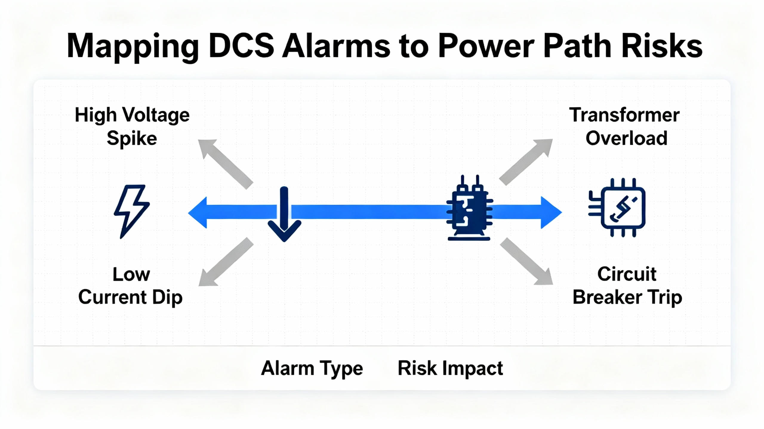
Mapping DCS Alarms to Power Path Risks
For power reliability, interpret alarms in terms of their risk to the critical load. A DC bus high condition on a large VFD that supplies chilled water can propagate as higher data center temperatures within minutes if the drive trips repeatedly; treat it as a plant stability issue and address braking or deceleration at the source. A communication fault on a controller that supervises fuel day tanks can be more serious than it looks if it disables automatic transfer or forces manual operation during a storm; confirm that fail-safe states and interlocks function as designed while you restore communications. Memory-card and configuration alarms on DC drives often surface after maintenance windows and controller swaps; resolve them quickly with the correct card and parameter set before you restart major equipment. Reframing device faults in terms of UPS runtime, generator start readiness, and cooling capacity helps dispatch the right expertise and prioritize work when multiple alarms compete for attention.
Model-Specific References and Why They Matter
Code definitions can change between families and software generations, as the published examples already demonstrate. One source documents F0002 as overcurrent, another as overvoltage, and both are accurate in their respective contexts. DC families like DCS 500 and DCS 800 use different alphabets and ranges for similar phenomena, and application-level alarms can be user-defined. The only safe path is to pair each DCS-integrated device with its official manual and keep the current parameter set saved. Brief public lists are helpful for triage, but final actions need a model-specific reference so you avoid treating a symptom from the wrong side of the protection curve. When in doubt, consider the integrated alarm guidance from ABBŌĆÖs operations and alarm-management materials, which emphasize context, grouping, and targeted navigation to the specific sources operators need in the moment.
Practical Field Habits That Reduce Recurrence
In the field, two habits pay for themselves. The first is to maintain a routine of backing up drive parameters and firmware baselines and saving copies in a place that the DCS incident reports can reference. When a configuration fault or compatibility warning appears, you can restore a known-good state rather than rebuild under pressure. The second is to treat nuisance alarms as defects rather than background noise. If thresholds are too tight or a sensor drifts, alarm floods desensitize operators and hide critical events until they become trips. Make it standard practice to review incident reports and adjust thresholds, remediate defective sensors, and de-duplicate alerts that carry the same operational meaning. Teams that do this well see fewer false positives and faster, calmer responses when the alarms that remain truly matter.
Short FAQ
What should I do when a DCS alarm label conflicts with a deviceŌĆÖs code list? Start with the deviceŌĆÖs own manual and parameter backup for the exact model and software. Consider the public triage examples as orientation, not authority, and update the DCS alarm text if it is misleading so future operators see the correct meaning.
How can I tell if a serial communication issue is cabling or configuration? Check the function blockŌĆÖs enable and connection status and verify addresses, baud rate, and parity against the device first. Confirm that the masterŌĆÖs transmit activity is present and use the correct pre-made ABB programming cable for local diagnostics. Only after parameters and physical-layer checks are complete should you suspect controller hardware.
When should I escalate a recurring power-stage trip to service? Escalate when the same fault repeats after you have addressed the common causes documented for that code and verified cooling, supply quality, mechanical load, and parameter settings. Internal fault indicators and persistent checksum or memory-card errors are also clear triggers for service or planned replacement.
References
| Publisher | Coverage as used here |
| ABB | Operations and alarm management concepts; model-specific manuals for System 800xA and ABB drives inform alarm context and workflow expectations |
| Automation & Control Engineering Forum | Practitioner guidance on 800xA serial communications using CI853, proper cable use, and master-slave behavior interpretation |
| Delta Automation | Practical drive troubleshooting techniques to decode and correct common ABB VFD faults with action-oriented remedies |
| Click2Electro | Brief list of common ABB VFD fault codes and first-line checks that highlight model variations in code definitions |
| Eltra Trade | Overview of ABB DCS 500 fault codes with definitions and suggested corrective actions for DC drives |
| ManualsLib | DCS 400 fault behavior and reset methods relevant to legacy DC drive integrations where DCS alarm resets differ from device-level requirements |
| Scribd | User-shared DCS800 alarm lists including memory-card and F501ŌĆōF509 examples, treated as starting points that require manual validation |
| ABB Ability Data Center Automation | Alarm grouping, response navigation to relevant displays, and incident reporting principles used to frame context-first alarm handling |
A reliable plant meets its promise when alarms earn attention and lead you straight to the cause. Treat codes as clues in context, validate meanings against the exact model, and keep your DCS alarms tied to the actions that restore margin. That is how you shorten outages and keep power where it belongs.
- https://open.clemson.edu/cgi/viewcontent.cgi?article=4460&context=all_theses
- https://repository.lib.ncsu.edu/bitstreams/1f58a837-4886-4e25-978c-e0142702a4f4/download
- https://upcommons.upc.edu/bitstreams/447f98e7-7d38-49de-842d-4f656657eb8b/download
- https://ww2.jacksonms.gov/browse/m238T1/2OK040/abb__dcs800__dc_drive_manual.pdf
- https://admisiones.unicah.edu/book-search/hdJBcM/2OK039/abb_800xa_pid__controller-manual.pdf
- https://www.longi.net/user-guide-for-abb-dcs550-series-dc-drives/?srsltid=AfmBOoqPk54YmnRKGrTnd2X0s0-eGm7cXoeMYhZQDitmuedTPTveVYWV
- https://seasons4.net/wp-content/uploads/2012/11/ABB-Fault-codes.pdf
- https://search.abb.com/library/Download.aspx?DocumentID=3ADW000379R&LanguageCode=en&DocumentPartId=&Action=Launch
- https://www.artisantg.com/info/ABB_DCS602_1500_61_15000A0_Manual_2019729162821.pdf?srsltid=AfmBOorPK1JHPsIzYofhU8Nsptk33wA8jVBoD99HsWCA0Kf4unAkN6AN
- http://www.foks.com.tr/downloads/ABB-DCS-Brosuru.pdf


 Videos
 News
News Applications


Leave Your Comment