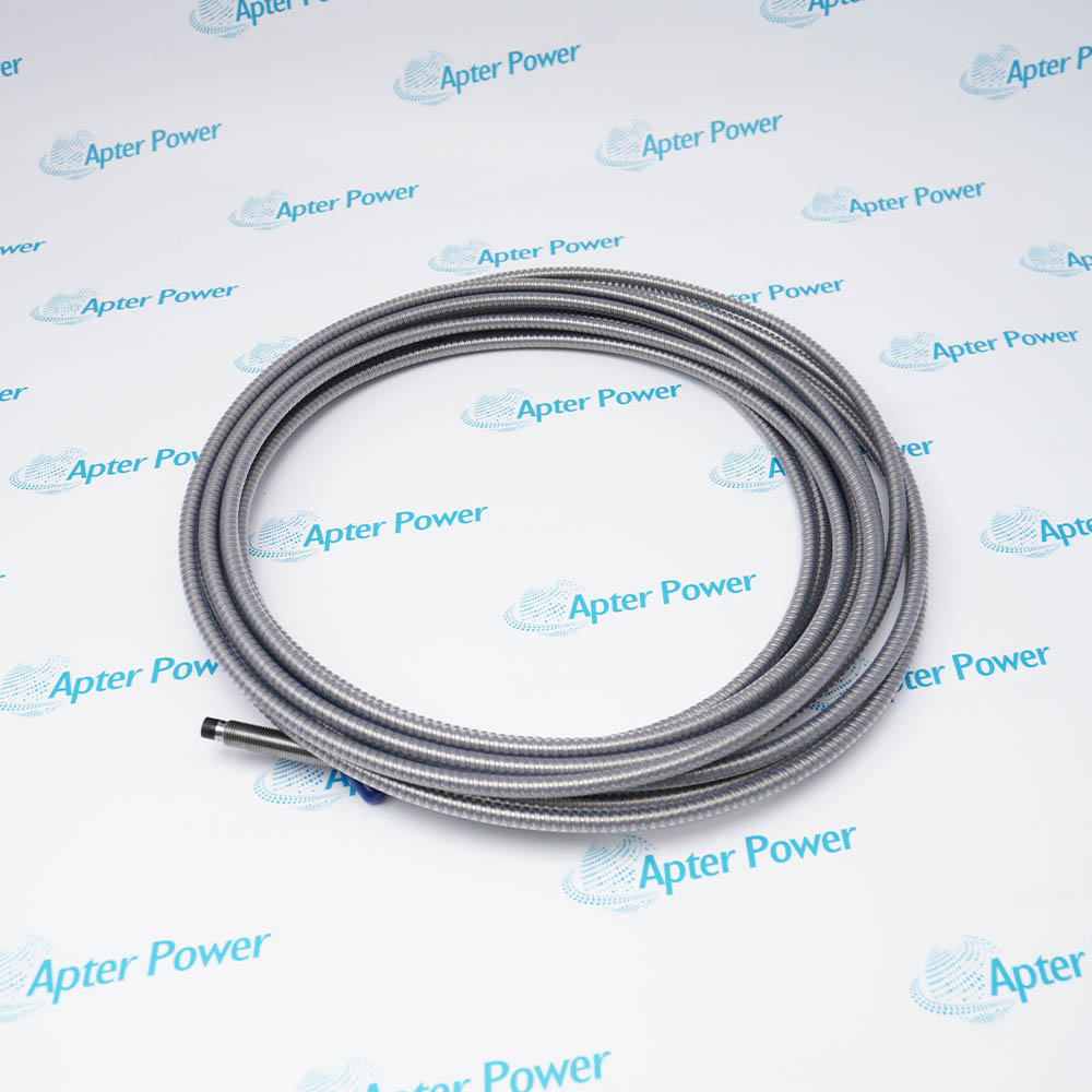
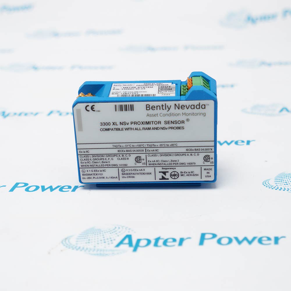
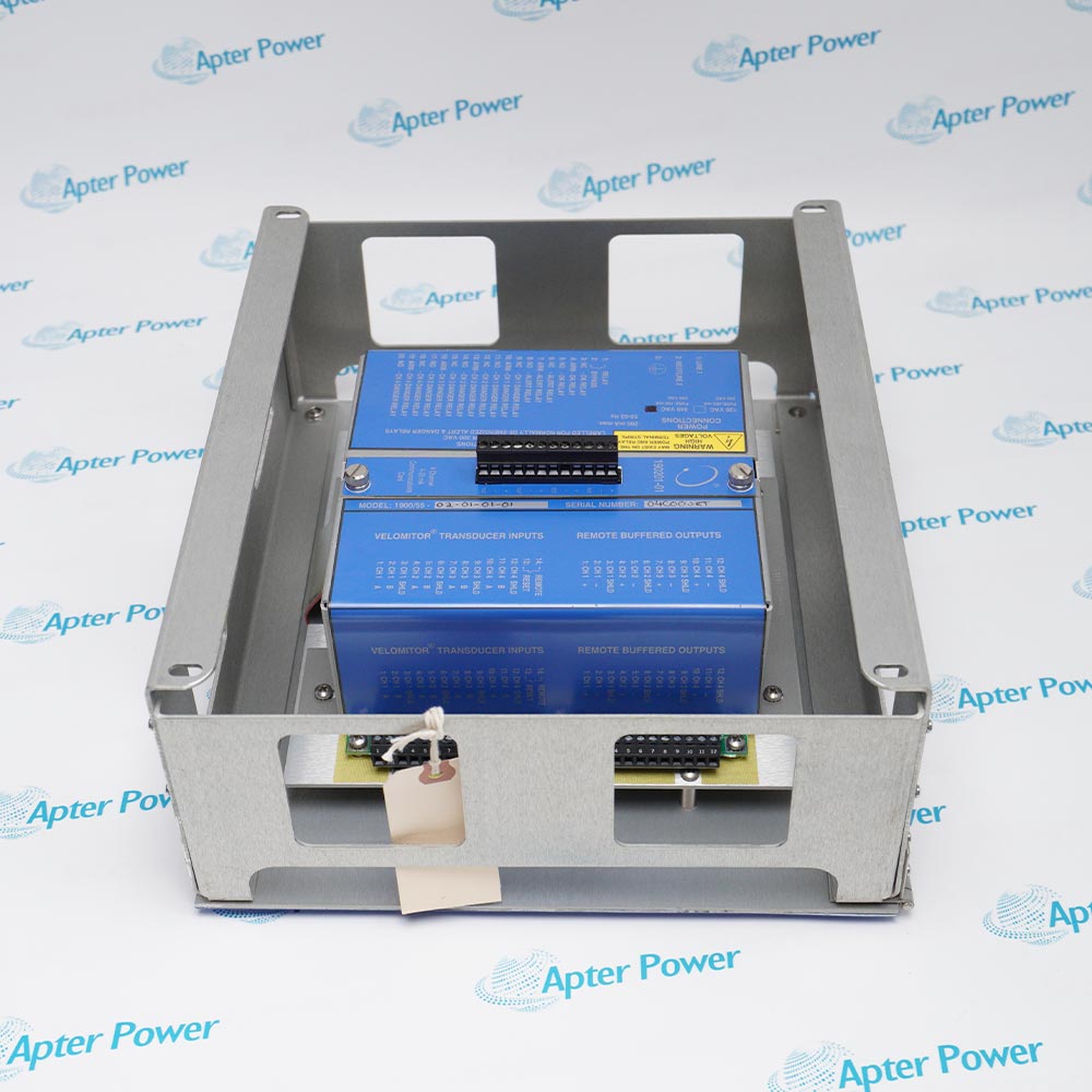
Converts machine-surface acceleration into a conditioned electrical signal for vibration monitoring and diagnostic systems.
- Signal or energy path: The piezoelectric sensing element and internal charge amplifier respond to casing motion, while the three-wire circuit carries the conditioned output to the connected monitor.
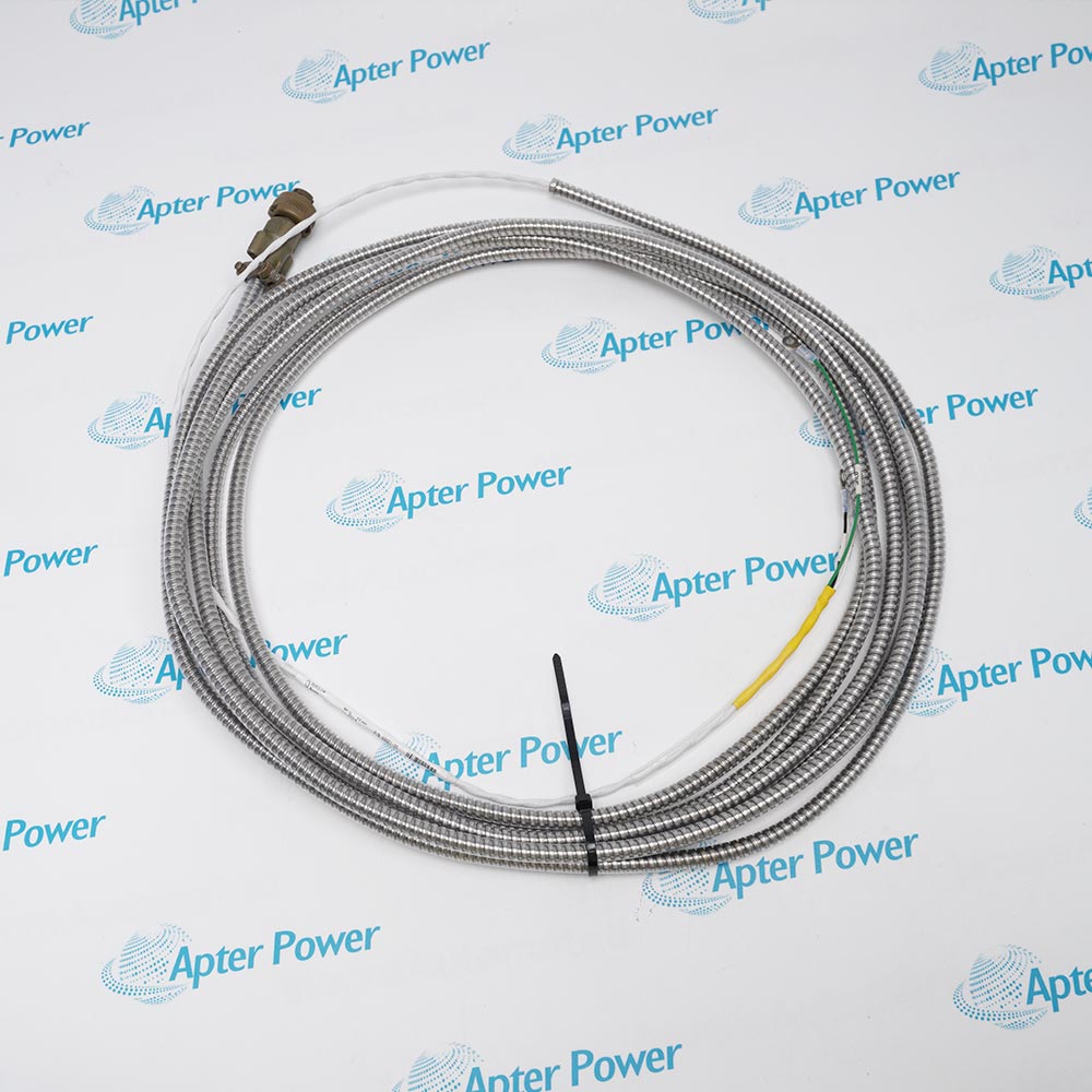
- Companion components: Use the specified mounting interface, low-noise cable, sensor power arrangement and compatible monitoring channel.
- Engineering check: Prepare a clean rigid mounting surface and verify orientation, cable strain relief, grounding and channel calibration.
- System boundary: The sensor output is valid only with the specified mounting, bias supply, cable and compatible monitoring input.
Casing-vibration measurement on motors, pumps, compressors, fans and other rotating machinery.
Important Notice: Verify the complete 330400-02-00 nameplate, installed-system documentation, companion hardware and current Bently Nevada instructions before installation or replacement.
Apter Power 330400-02-00 Manuals and Guides
Important Notice: The first link is the product-parameters PDF prepared only from the cited manufacturer information; the second link is the Apter Power product manual. Confirm the physical nameplate, current manufacturer documents, and host-system requirements before installation or replacement.
Gear-mesh acceleration monitoring
Measures high-frequency casing acceleration on a gearbox or geared critical machine where gear-mesh vibration is transmitted to the selected bearing housing or casing point.
Reciprocating-compressor impact monitoring
Feeds a compatible monitor such as 3500/70M with acceleration data used for high-frequency impact and gas-leak-related signatures on reciprocating machinery.
Hydro-unit casing acceleration
Connects to a compatible 3701/46 PAS or PAV acceleration input for continuous casing or bearing-housing measurements on a hydro unit.
Legacy three-wire accelerometer upgrade
Provides a backward-compatible three-wire sensor architecture for replacing older 23732-type acceleration systems without an external interface module, after monitor and wiring verification.
Read and follow the current Bently Nevada documentation and host-equipment instructions before work. Verify the complete physical nameplate and system configuration.
1
Treat 330400-02-00 as agency-approval option 00: do not claim or use CSA, ATEX or IECEx certification from the -05 option or family approval section; select the exact approved part when the area classification requires it.
2
Install the M8 x 1 stud on a properly prepared bearing housing or machine casing at 4.1 N·m and at a location that actually transmits rotor vibration; poor mounting can reduce amplitude/frequency response or create false signals.
3
Use a monitor that supplies the documented -24 ±0.5 VDC three-wire PWR/SIG/COM interface and 100 mV/g scaling; do not wire it as a two-wire IEPE sensor or as a 4-20 mA device.
4
Keep vibration, temperature and frequency inside the published limits; energy above 15 kHz, especially near resonance, significantly reduces the stated 50 g measurement range, and the IP68-equivalent statement applies to the sensor rather than its cable.
5
Match the three-pin connector and cable, protect outdoor wiring in conduit/enclosure as documented, and use mounting base 37439-02 on pre-April-2004 non-G serial-number units to reduce base-strain sensitivity.


 Videos
 News
News Applications